This little power supply board plugs into a ProMini shield stack or the ProMini Backplane boards that I designed. It's basic but it has a couple of nice features.
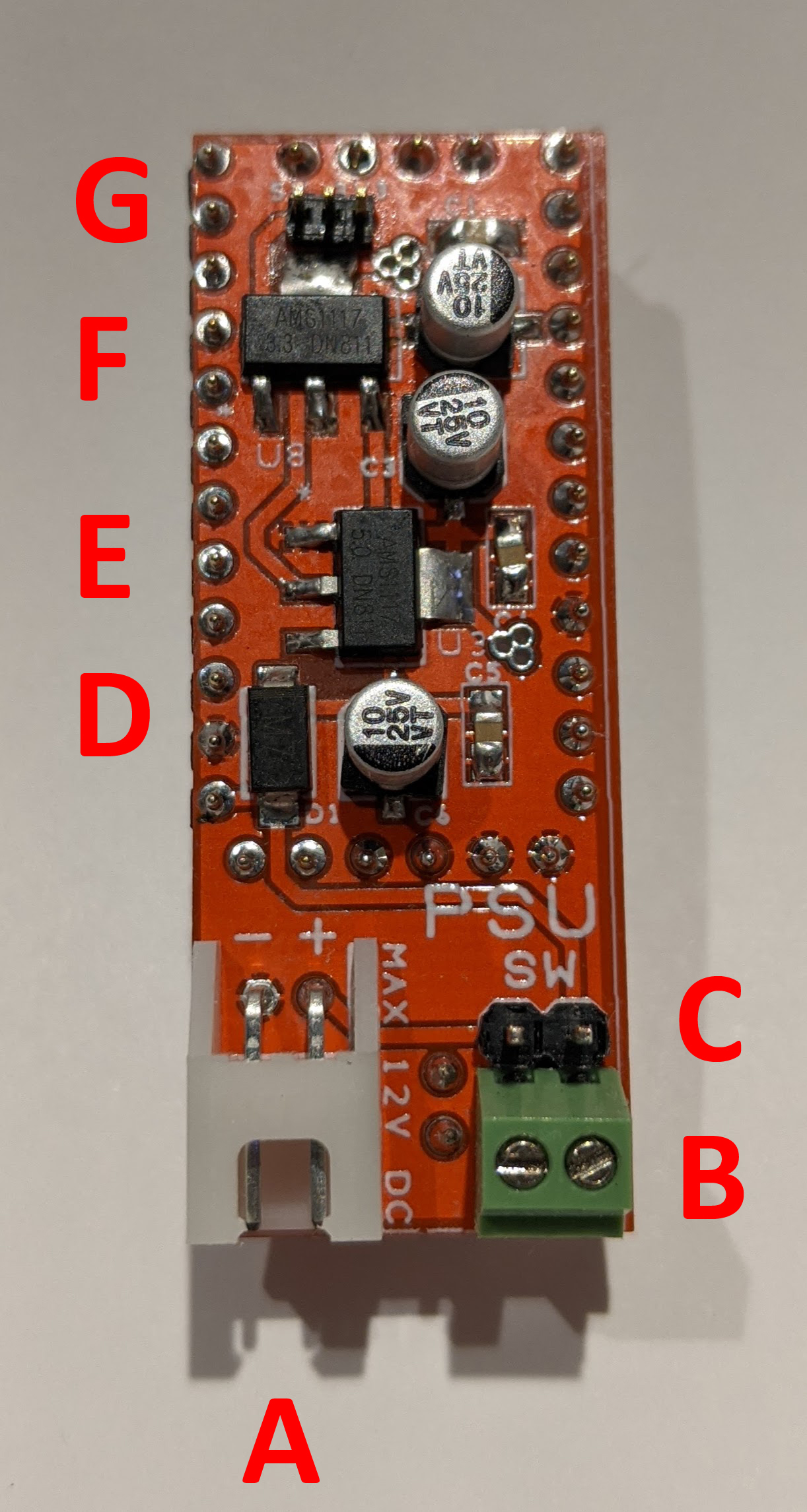
In this top view:
A - Power inlet
B - Screw terminals for offboard switch
C - Jumper across switch screw terminals
D - Reverse current protection diode
E - 5V regulator
F - 3.3V regulator
G - 3.3V/5V on Vcc rail jumper
The switch screw terminals let me use an external switch to turn the power supply on and off. If I'm not using an external switch I can use the adjacent jumper to tie the power supply on or I can put the jumper on and take it off to turn the power supply on and off.
The power supply puts the supply voltage from the power connector onto the Vin rail on the ProMini Backplane board. There is a jumper on the next slot over to allow me to take Vin off that socket so that I can put the ProMini in there and not have it powered all the time.
You can see two round pads between the white power inlet connector and the green screw terminals. This is an optional 2-pin header that sends regulated 3.3V and 5V from the power supply board down to the ProMini Backplane board to supply screw terminals to allow me to power offboard sensors or other devices easily.
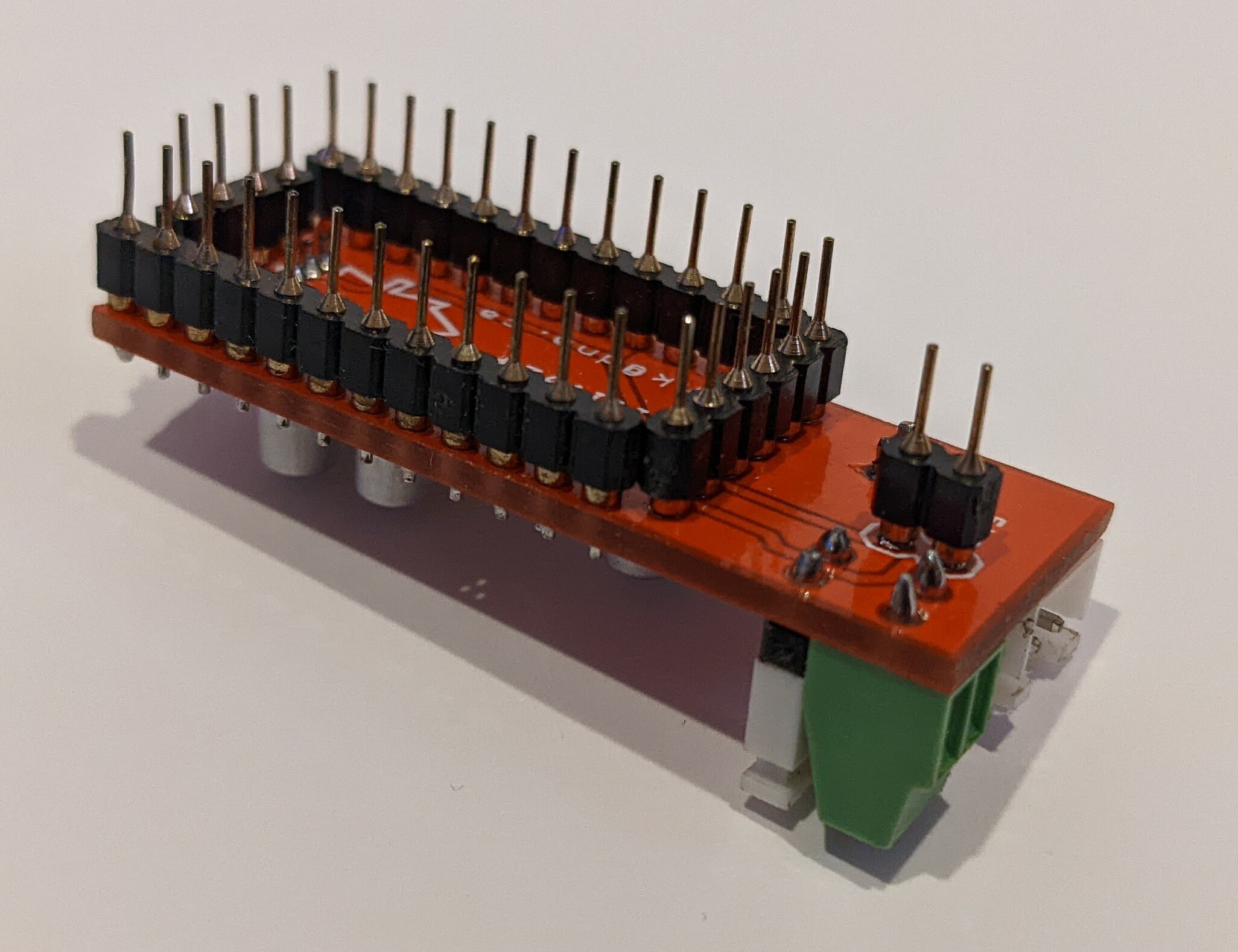
You can clearly see the extra 2-pin connector in this bottom shot.
This board was designed in DS PCB before I switched to Pulsonix. I had them made by All PCB and assembled them by hand. This was a fun little project and I use these little boards quite often.
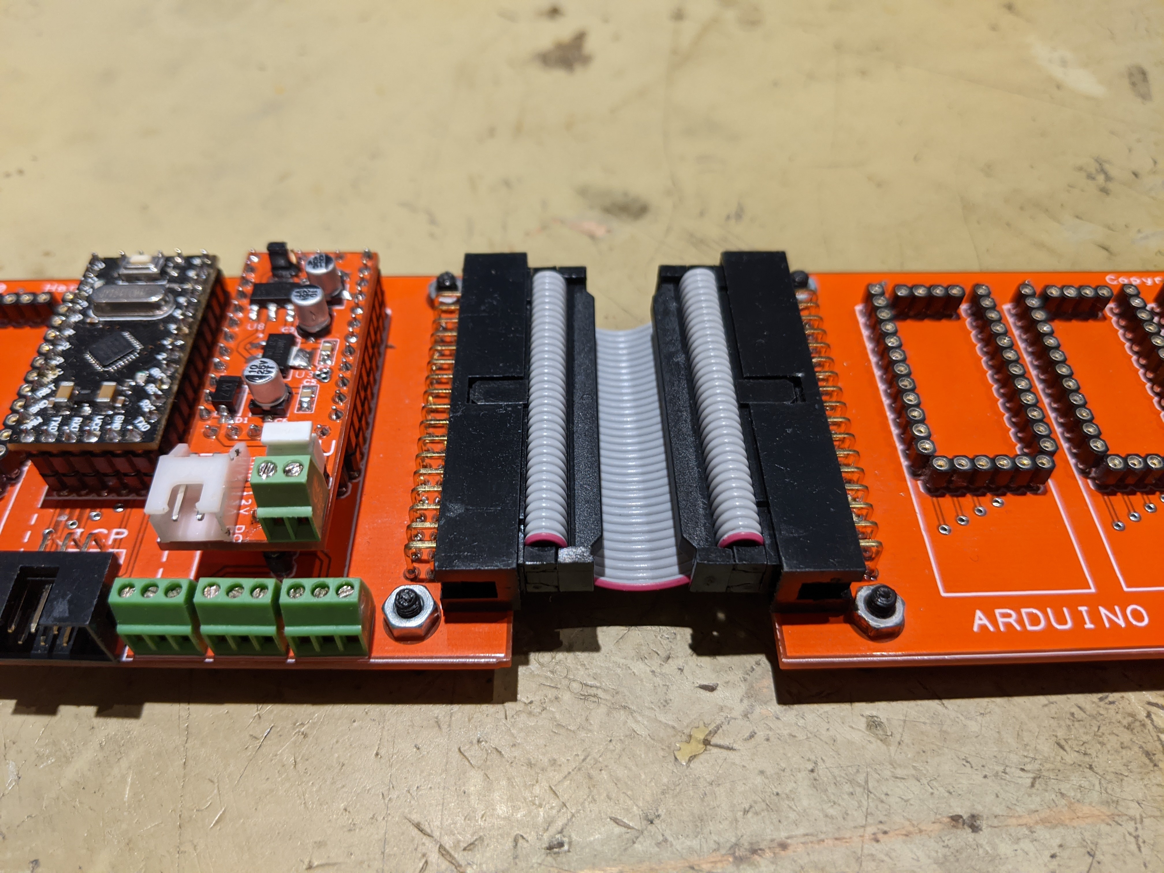
Here it is in action. The PSU board and a ProMini installed on the left ProMini Backplane board. You can see the 5V, GND, and 3V3 screw terminals to supply offboard power. I've also got two Backplane boards daisy chained together. You can also just see the 6-pin ICP port to the left of the screw terminals.
