Arduino
532 readers
9 users here now
This is an UNOFFICIAL Arduino community.
Everyone who uses Arduino board or their clones or associated boards and/or the Arduino IDE is welcome here. If it involves Arduino hardware or software it's welcome here. If it connects to Arduino hardware it's welcome here. If you're building your own boards that you use with an Arduino it's welcome here. There will be no Arduino elitist bullshit in this community.
You may also be interested in:
RULES:
-
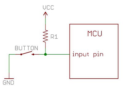
It's always a floating input.
-
All Lemmy.ca rules apply here.
-
Everyone (see rule 98) is welcome.
-
If you’ve seen a question 100 times answer it the 101st time or ignore it. Even better, write a complete, detailed answer and suggest that the mod(s) pin it to the community.
[Did you actually think there were 98 rules?]
-
If you present something as fact and are asked to provide proof or a source provide proof or a source. Proof must be from a reliable source. If you fail to provide proof or a source your post or comment may be removed.
-
Don’t be a dick. Yes, this is a catch-all rule.
-
The mod(s) have the final say.
founded 1 year ago
MODERATORS
1
If your circuit is behaving weirdly, switching on when you touch a wire or move your hand over the circuit you almost certainly have a floating input. You can solve this problem with a pull-up resistor. Many AVRs have built-in pull-up resistors that you can turn on using code.
In Sketch:
pinMode(2, INPUT_PULLUP);
In BascomAVR:
Config Portb.1 = Input Set Portb.1
There's a great article at SparkFun about Pull-up Resistors.
2
3
Crossposted from: https://lemmy.ml/post/9698836
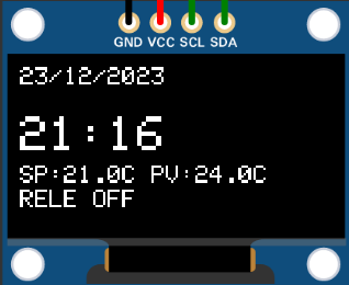
This setup allows Arduino to read temperature, control relay based on setpoints, display info on OLED screen, and manage date/time settings with user input through buttons. Adjust based on specific hardware/project requirements.
Designed to replace the faulty electronic control of a blue heat radiator.
Licensed under GNU GPLv3.
4
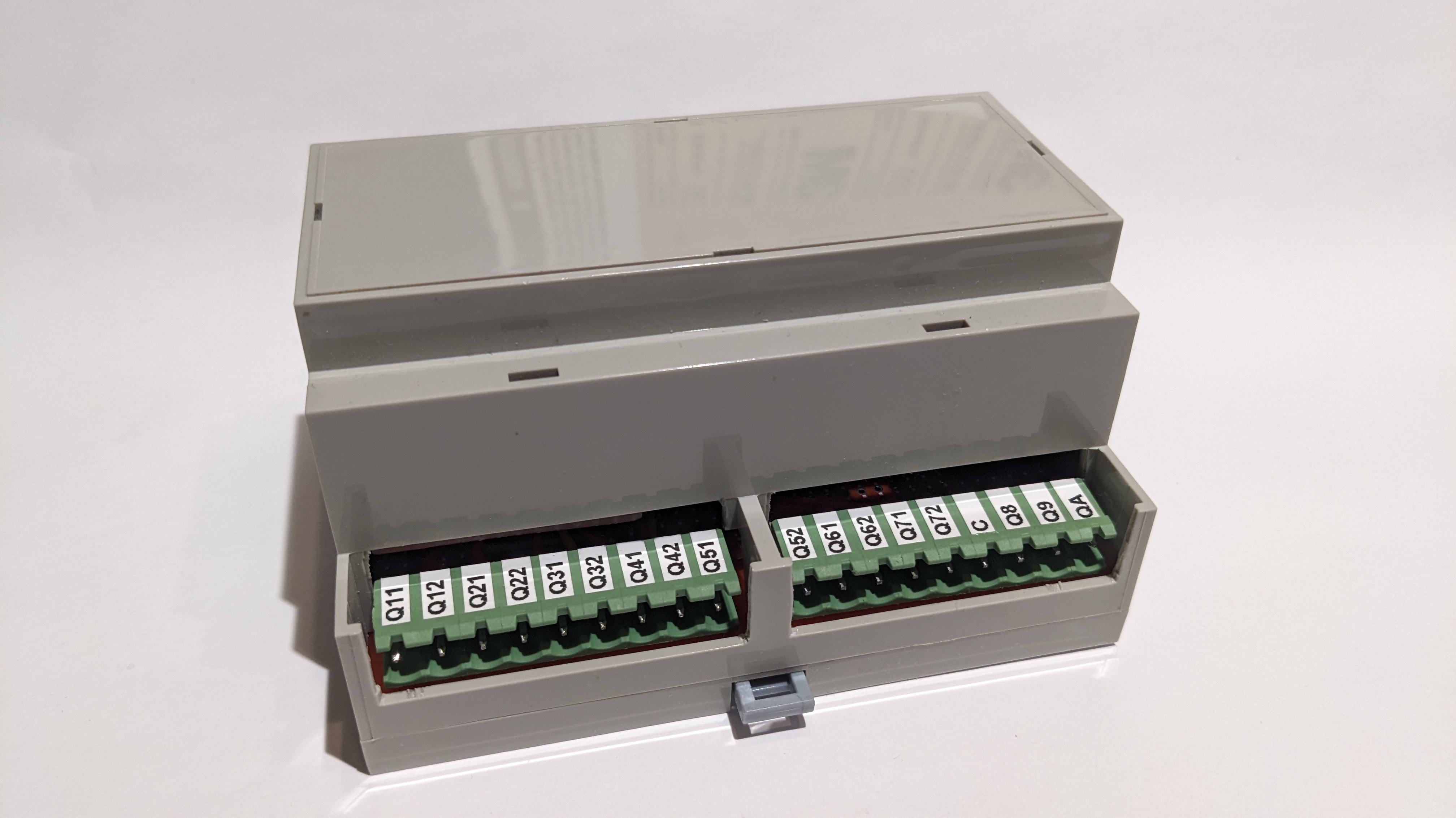
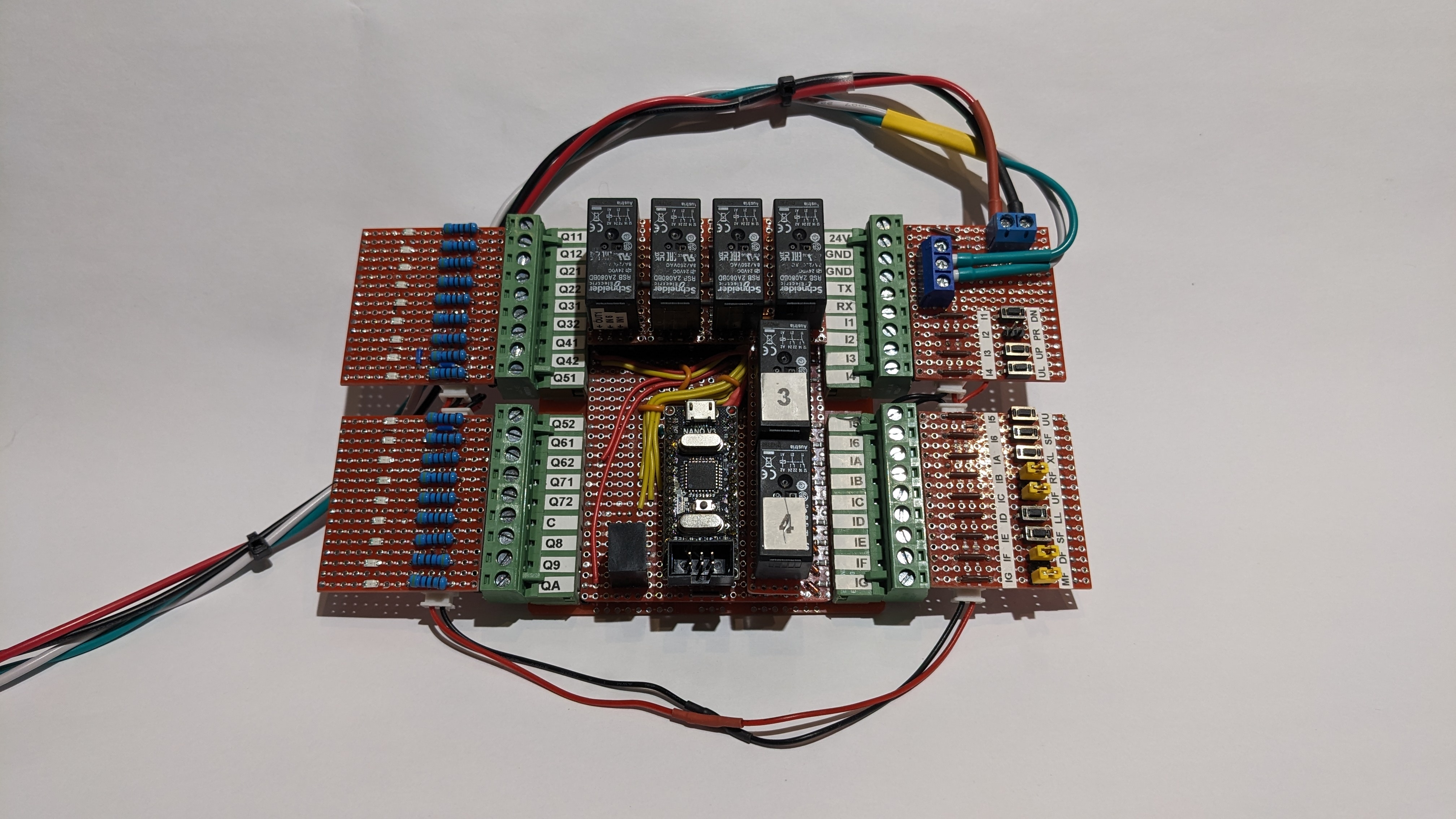
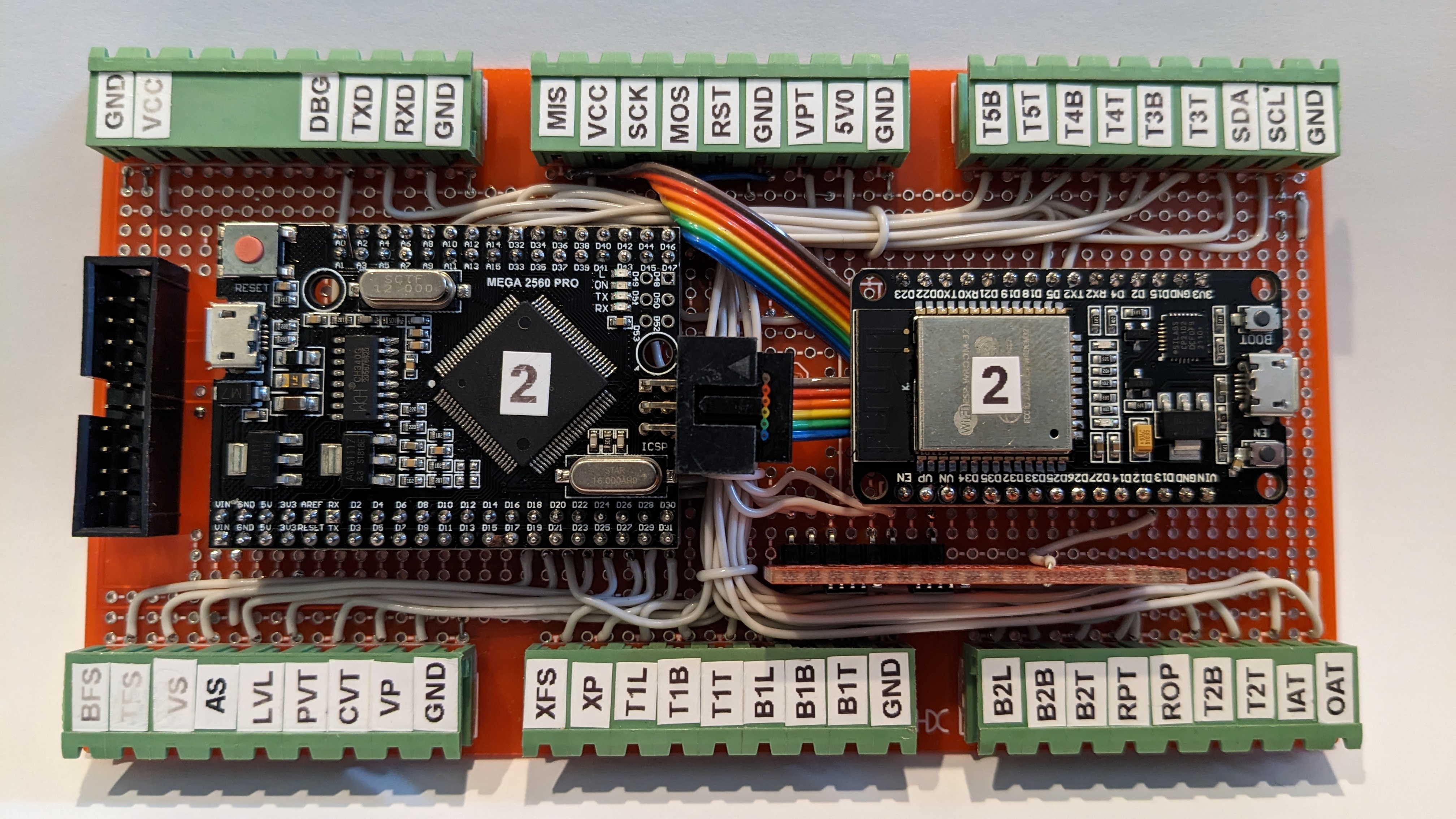
This is the replacement controller I built for the wheelchair lift. The controller itself is in the middle. The four board on the left and right are a testing harness. The red and black wires are 24VDC and the green and white ones TX and GND for monitoring with a terminal program on my notebook (puTTY).
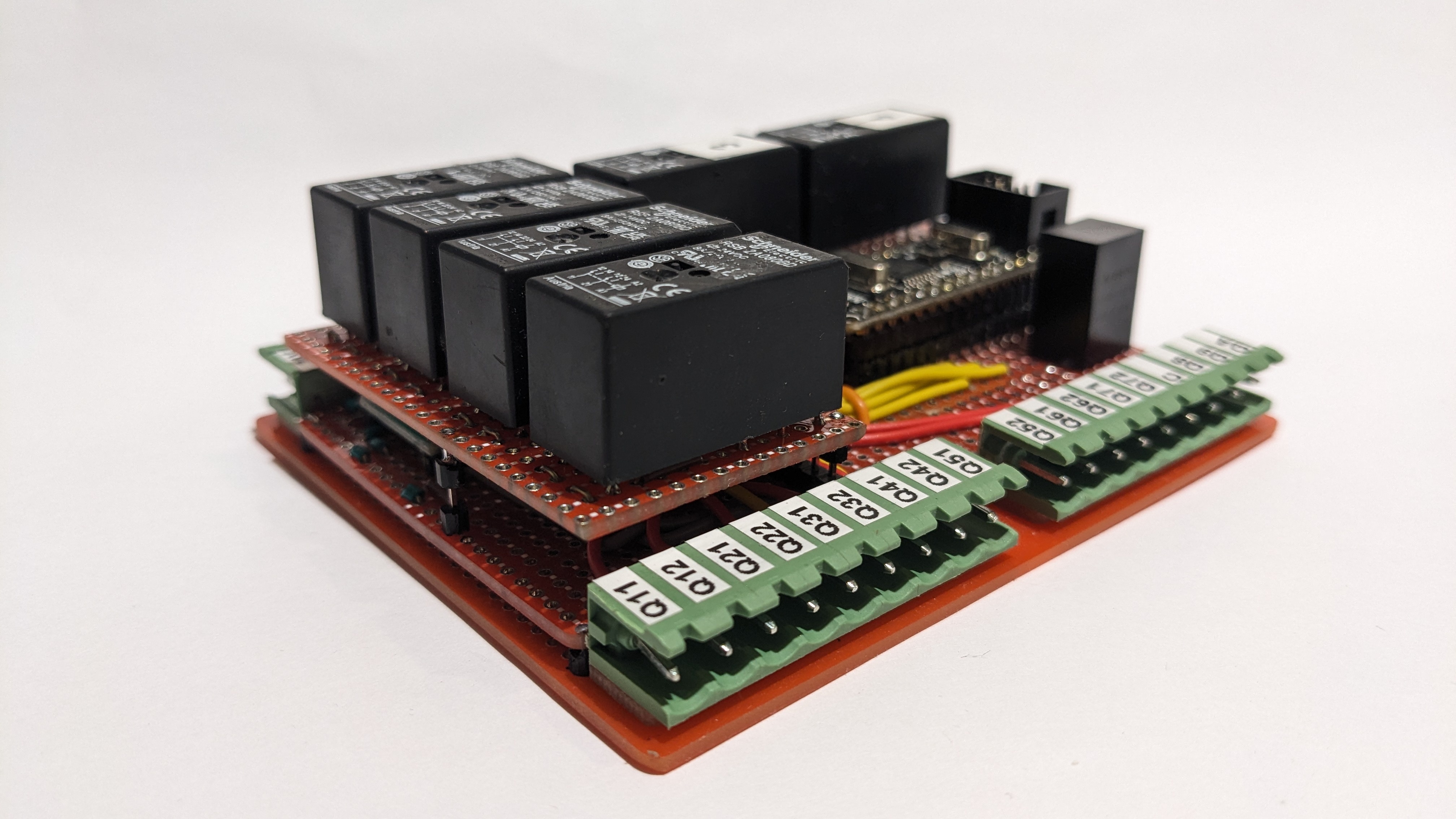
Without the test harness it looks like this.
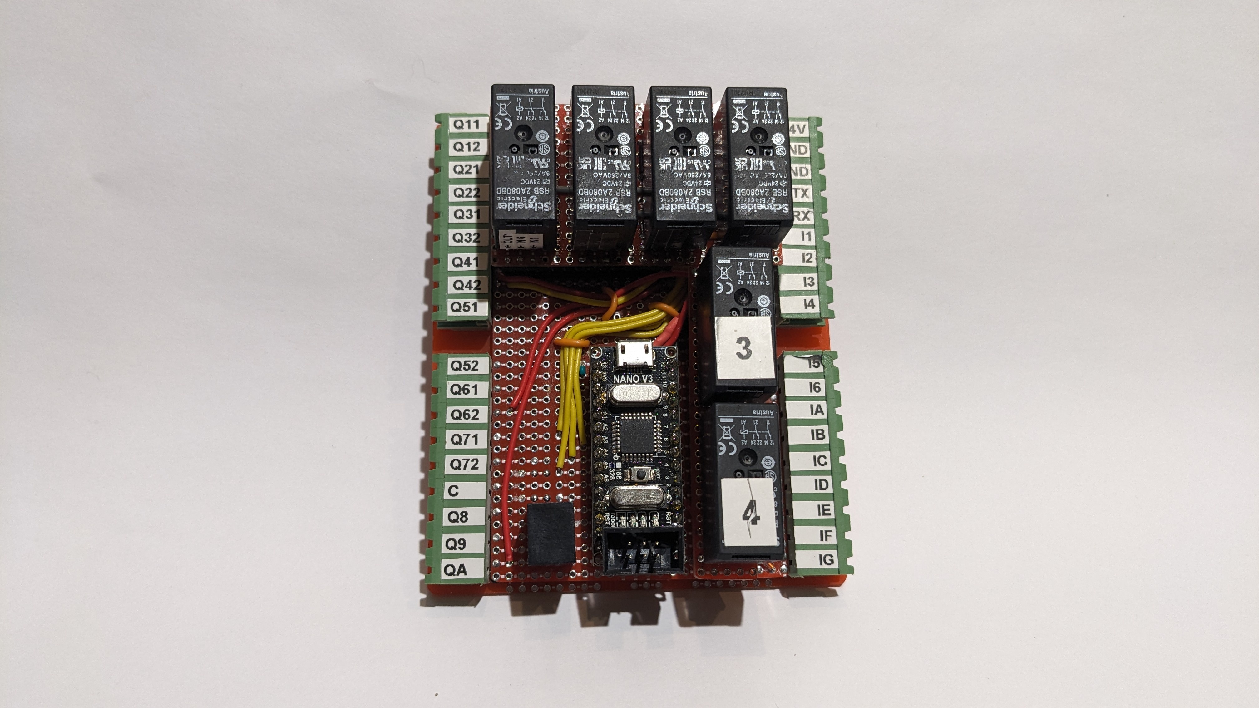
I was trying to squeeze a LOT into the BID box that I'm using for this project. I had to stack boards to get everything in.
The bottom most board is a standard bottom board for the BUD case. It has holes along each side for 2.54 screw terminals and pluggable screw terminals. I'm only using that board to mechanically connect the project to the BID case and for the screw terminals. I almost always use pluggable screw terminals because they're awesome. I can unplug four plugs instead of unscrewing 36 screw terminals and trying to keep the wires straight.
There are two top boards. The one on the left carries four relays which turn the negative logic of the Darlingtons into positive logic for the lift. They send 24VDC out to the contactors that run the motors and the door lock. The other small board at the rear has two safety relays which switch power coming in through a bunch of safety switches out to the battery relay and the main contactor.
This is what it looks like assembled into its BUD case.
This is all built around an Arduino Nano with a program that I wrote in Great Cow BASIC.
5
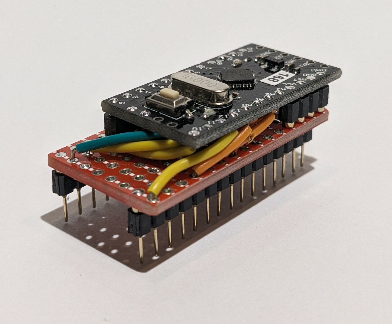
I give you Frankenduino. It's an Arduino ProMini soldered onto a piece of protoboard and wired up to the Nano pinout.
I have 10 Nanos on order but I really needed to keep the project moving.
This ProMini has an ATMEGAS168 chip on it but that's good enough for what I'm doing.
6
7
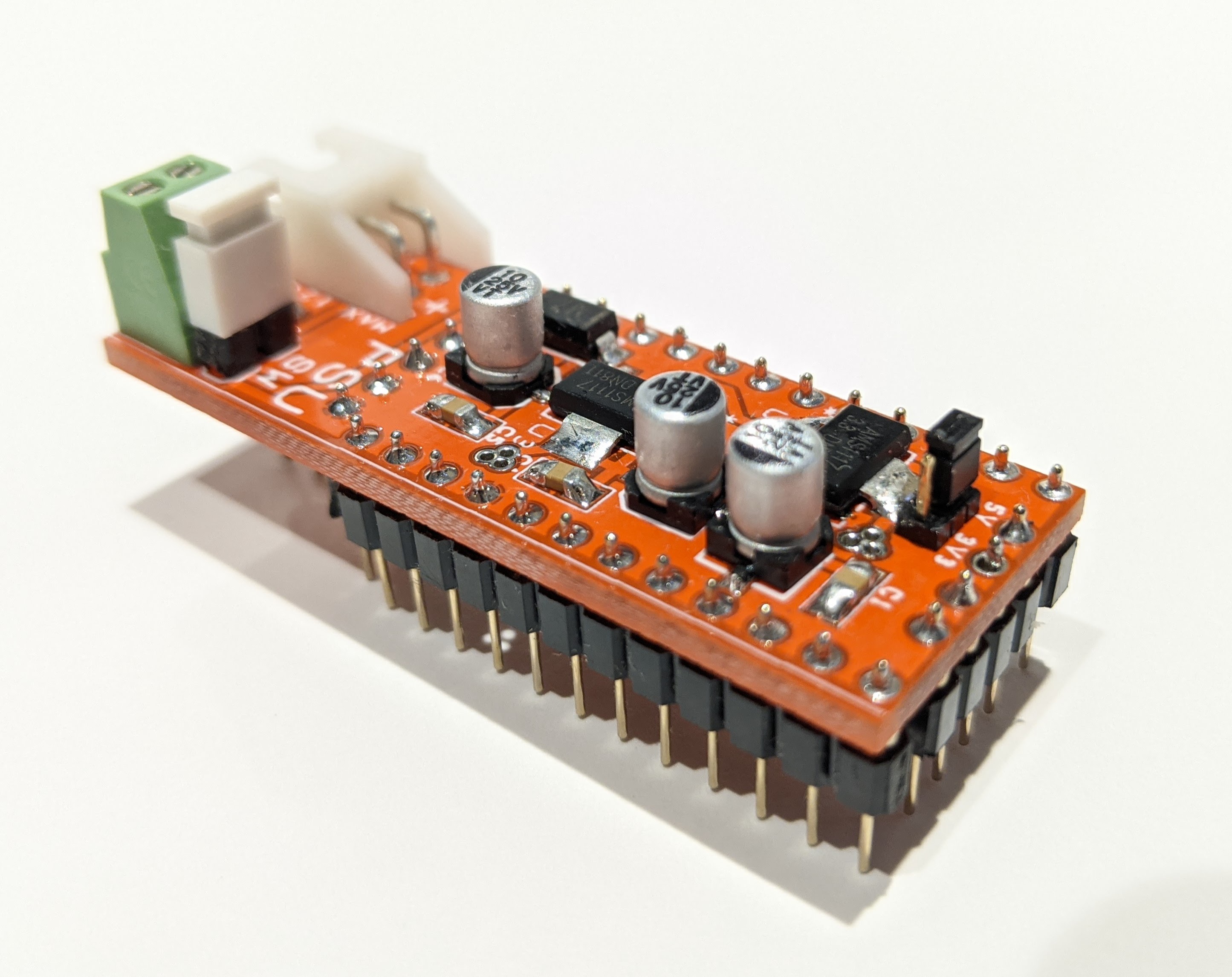
This little power supply board plugs into a ProMini shield stack or the ProMini Backplane boards that I designed. It's basic but it has a couple of nice features.
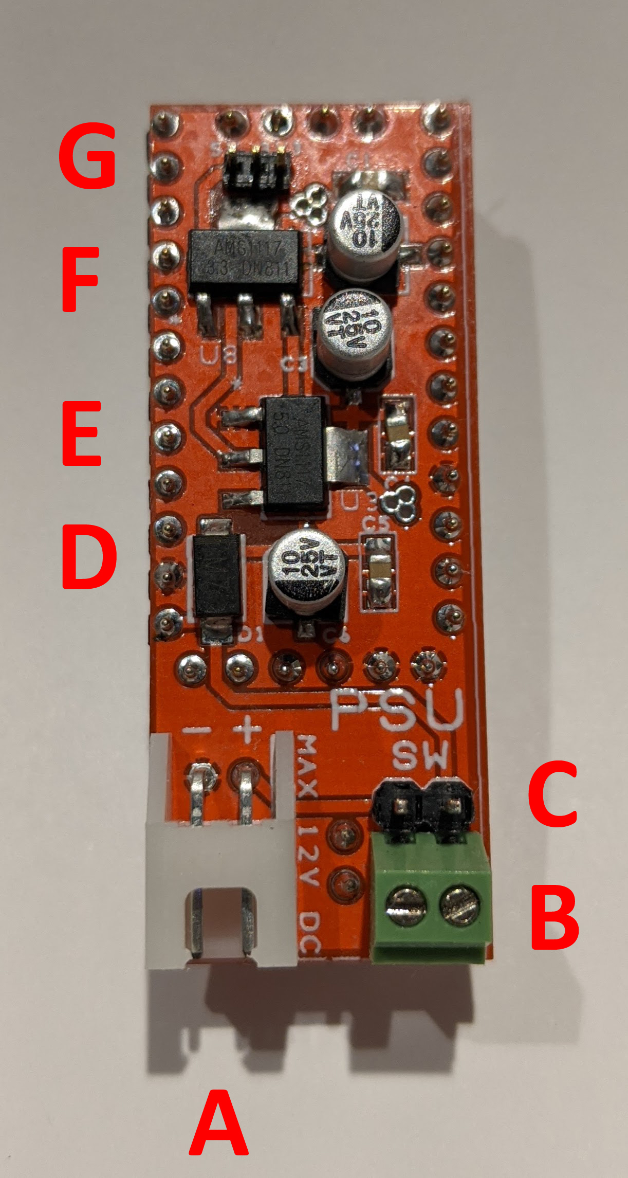
In this top view:
A - Power inlet
B - Screw terminals for offboard switch
C - Jumper across switch screw terminals
D - Reverse current protection diode
E - 5V regulator
F - 3.3V regulator
G - 3.3V/5V on Vcc rail jumper
The switch screw terminals let me use an external switch to turn the power supply on and off. If I'm not using an external switch I can use the adjacent jumper to tie the power supply on or I can put the jumper on and take it off to turn the power supply on and off.
The power supply puts the supply voltage from the power connector onto the Vin rail on the ProMini Backplane board. There is a jumper on the next slot over to allow me to take Vin off that socket so that I can put the ProMini in there and not have it powered all the time.
You can see two round pads between the white power inlet connector and the green screw terminals. This is an optional 2-pin header that sends regulated 3.3V and 5V from the power supply board down to the ProMini Backplane board to supply screw terminals to allow me to power offboard sensors or other devices easily.
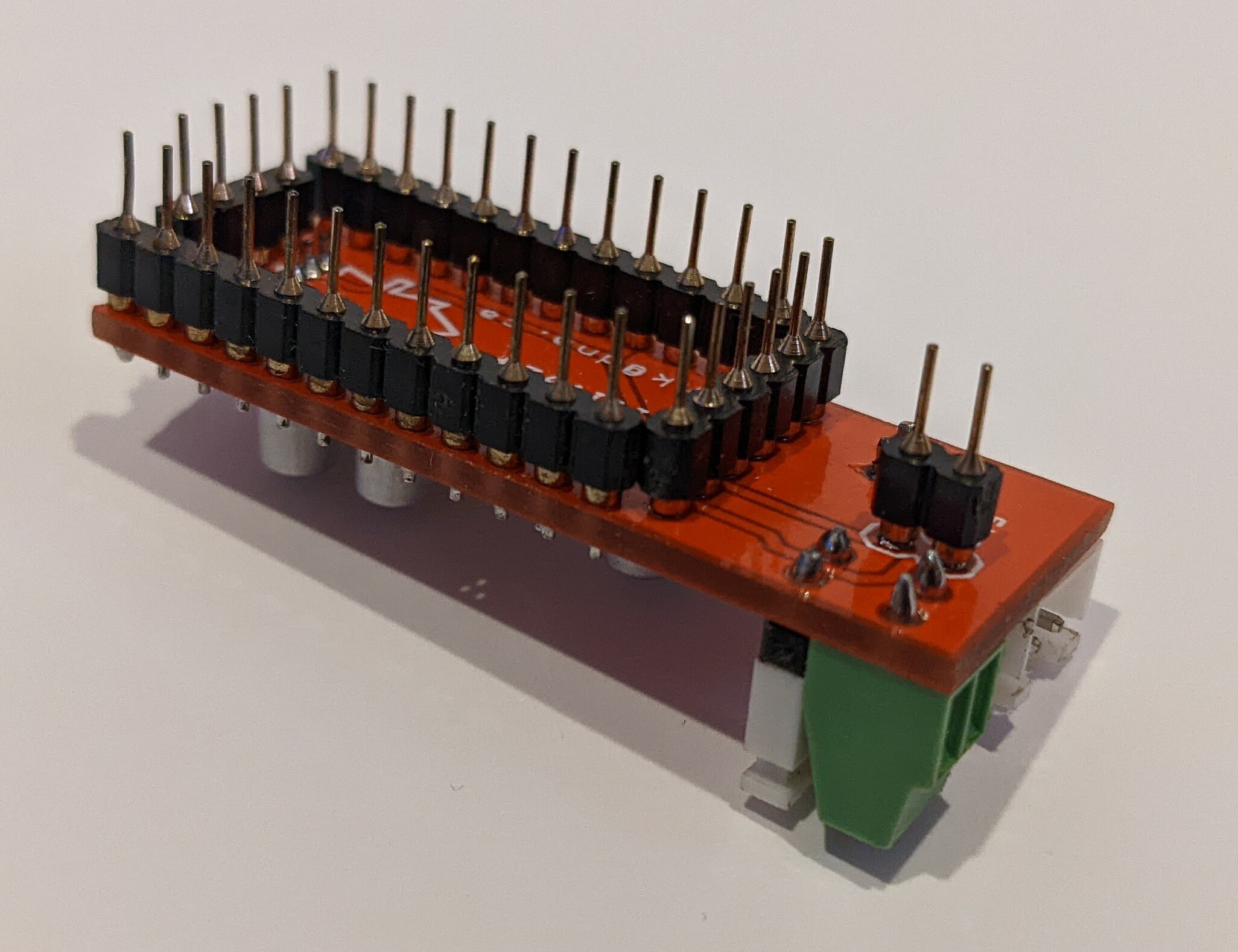
You can clearly see the extra 2-pin connector in this bottom shot.
This board was designed in DS PCB before I switched to Pulsonix. I had them made by All PCB and assembled them by hand. This was a fun little project and I use these little boards quite often.
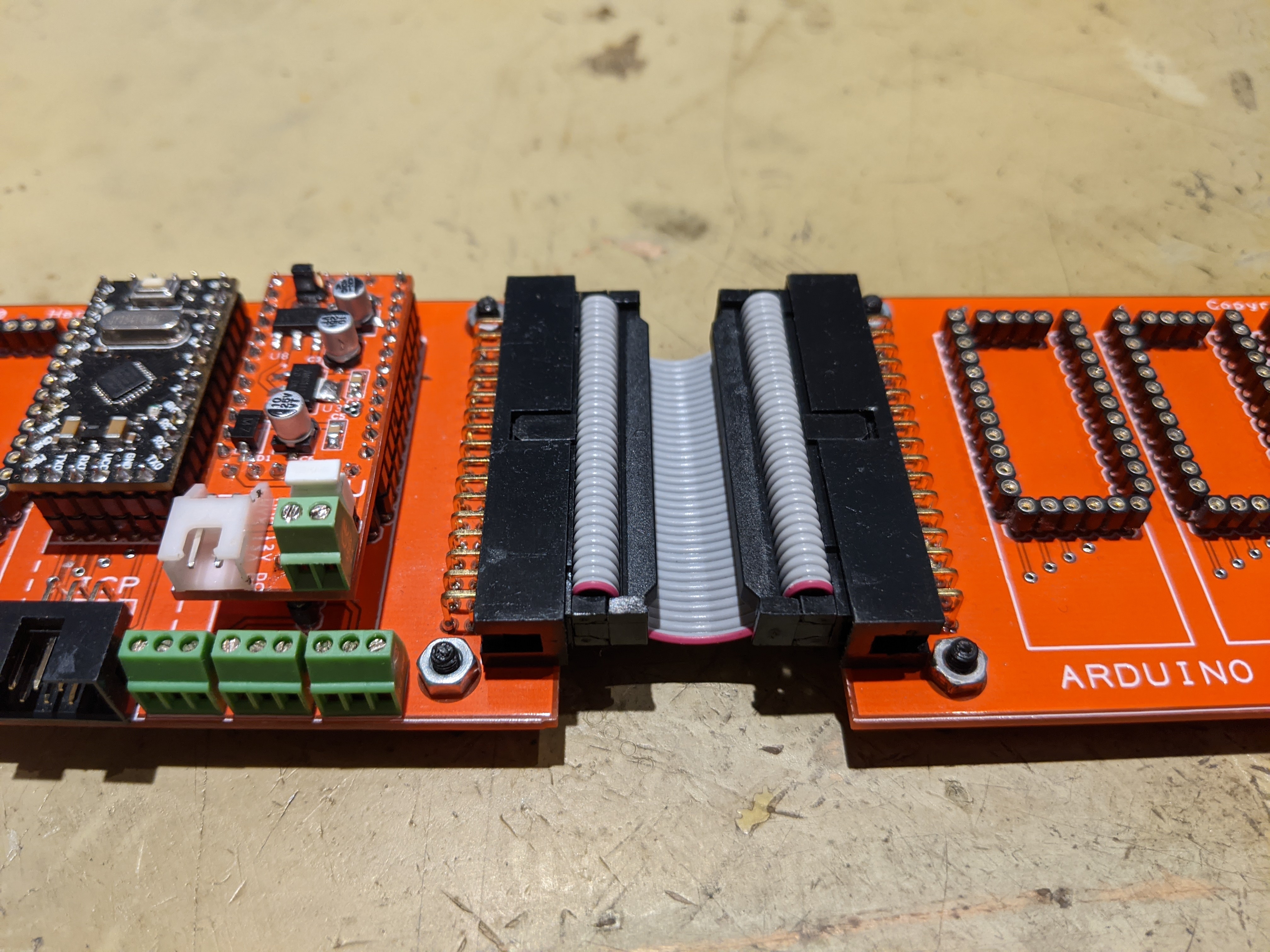
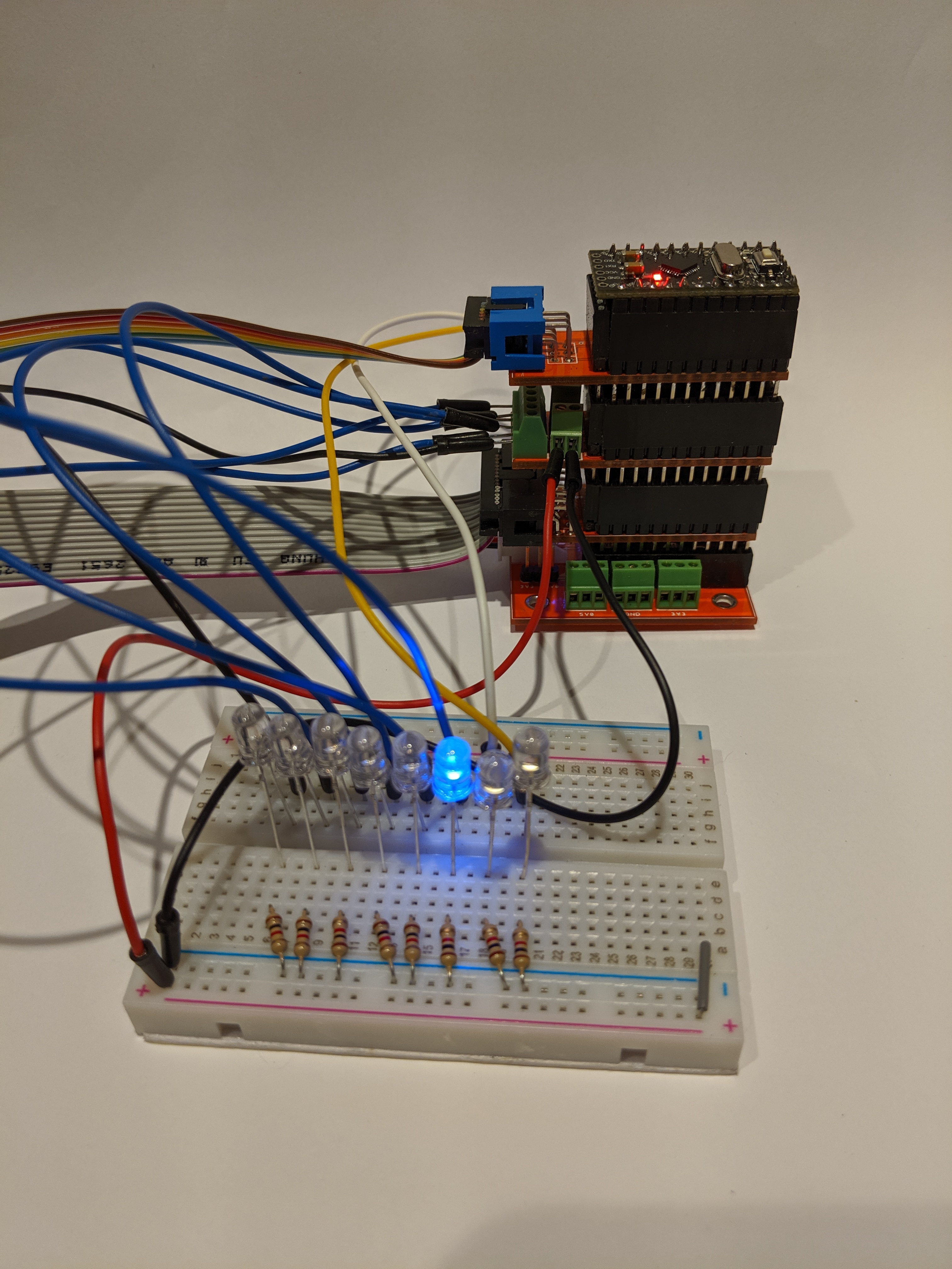
Here it is in action. The PSU board and a ProMini installed on the left ProMini Backplane board. You can see the 5V, GND, and 3V3 screw terminals to supply offboard power. I've also got two Backplane boards daisy chained together. You can also just see the 6-pin ICP port to the left of the screw terminals.

8
I needed some LEDs so that I could track what my data lines were doing. I started with a bunch of LEDs and resistors on a breadboard.
From there I made up a small block of SMD LEDs and resistors on a piece of proto board.
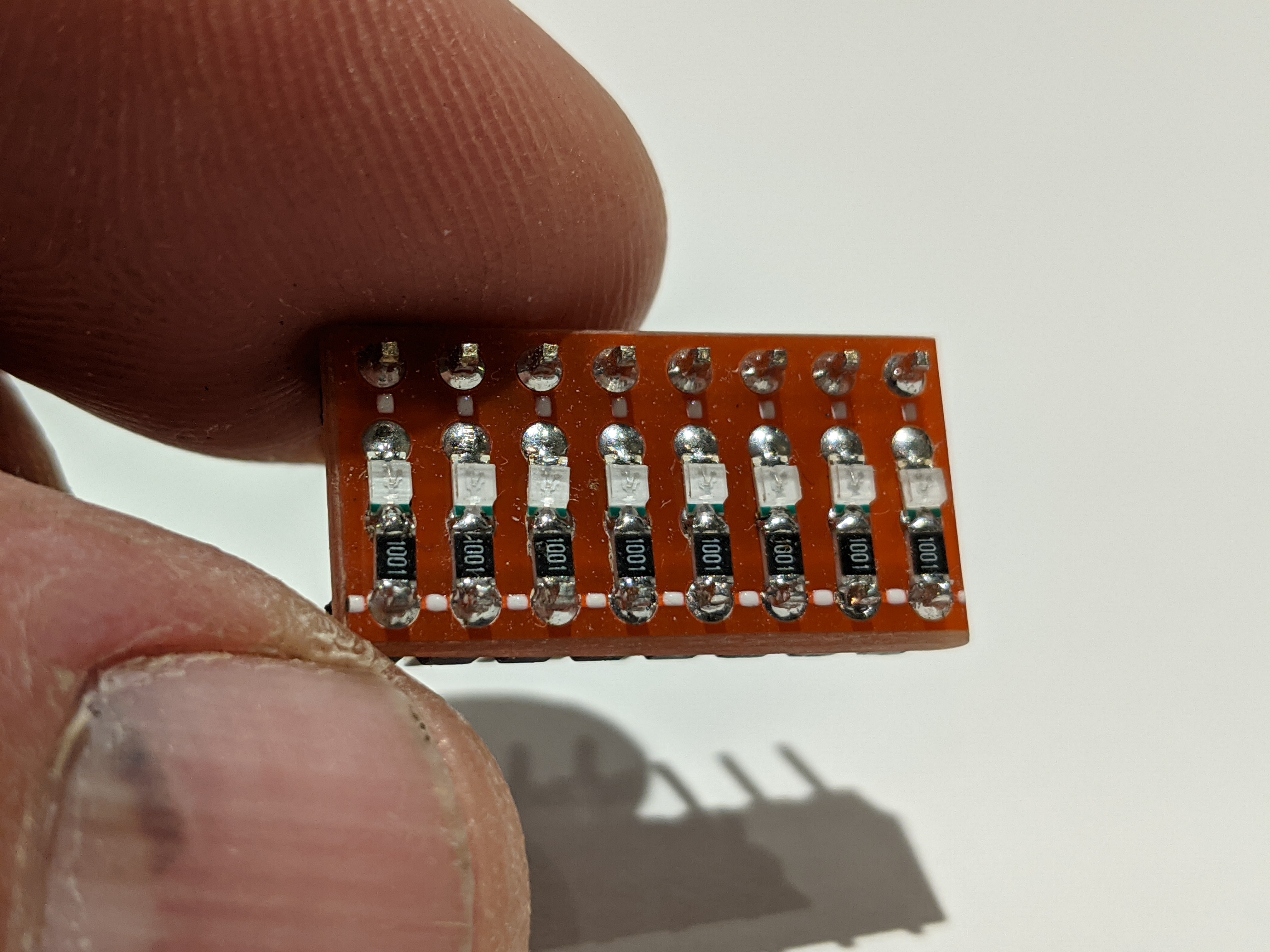
Then I moved to an actual prototype on a dedicated protoboard.
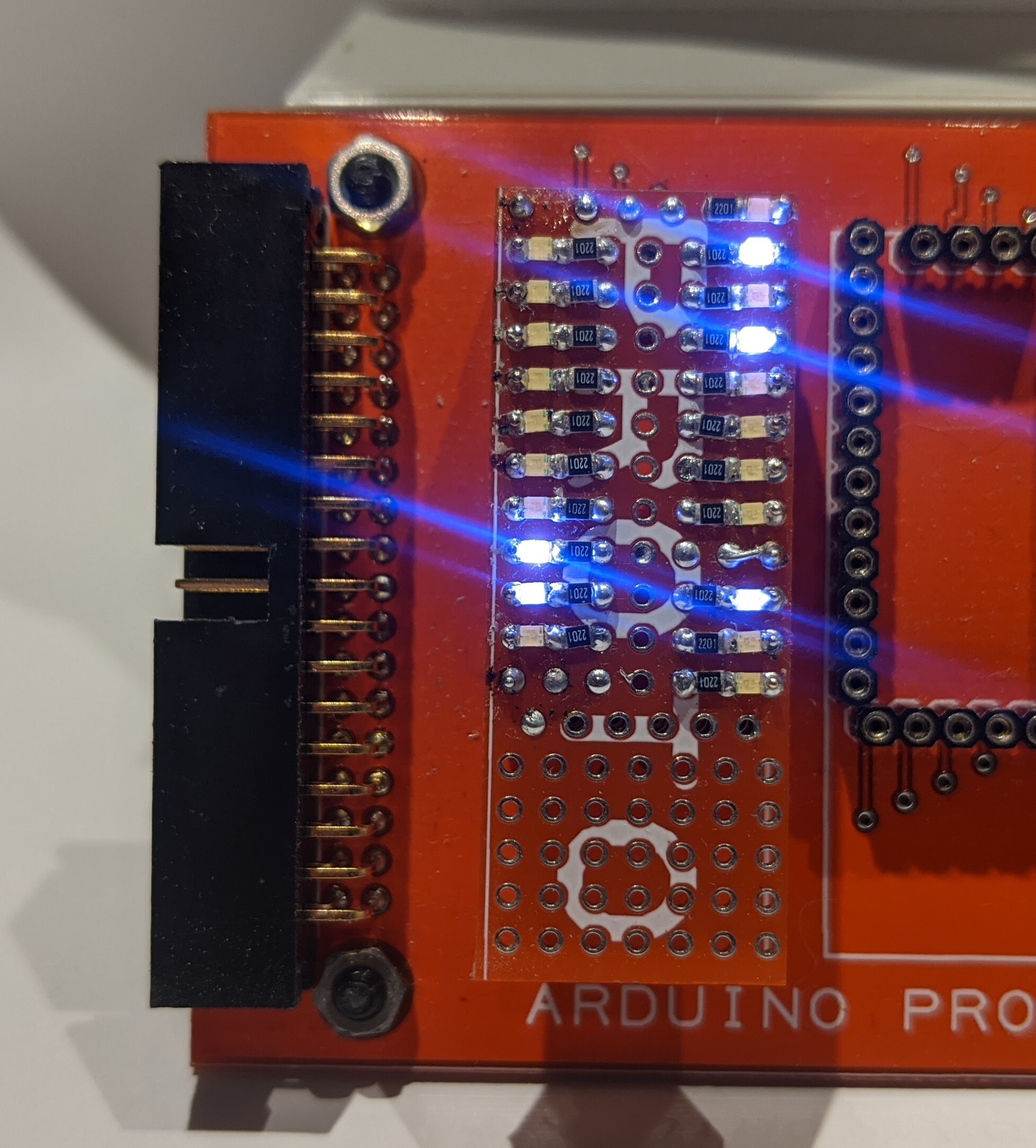
Finally, I produced the finished product. BLINKY LIGHTS!
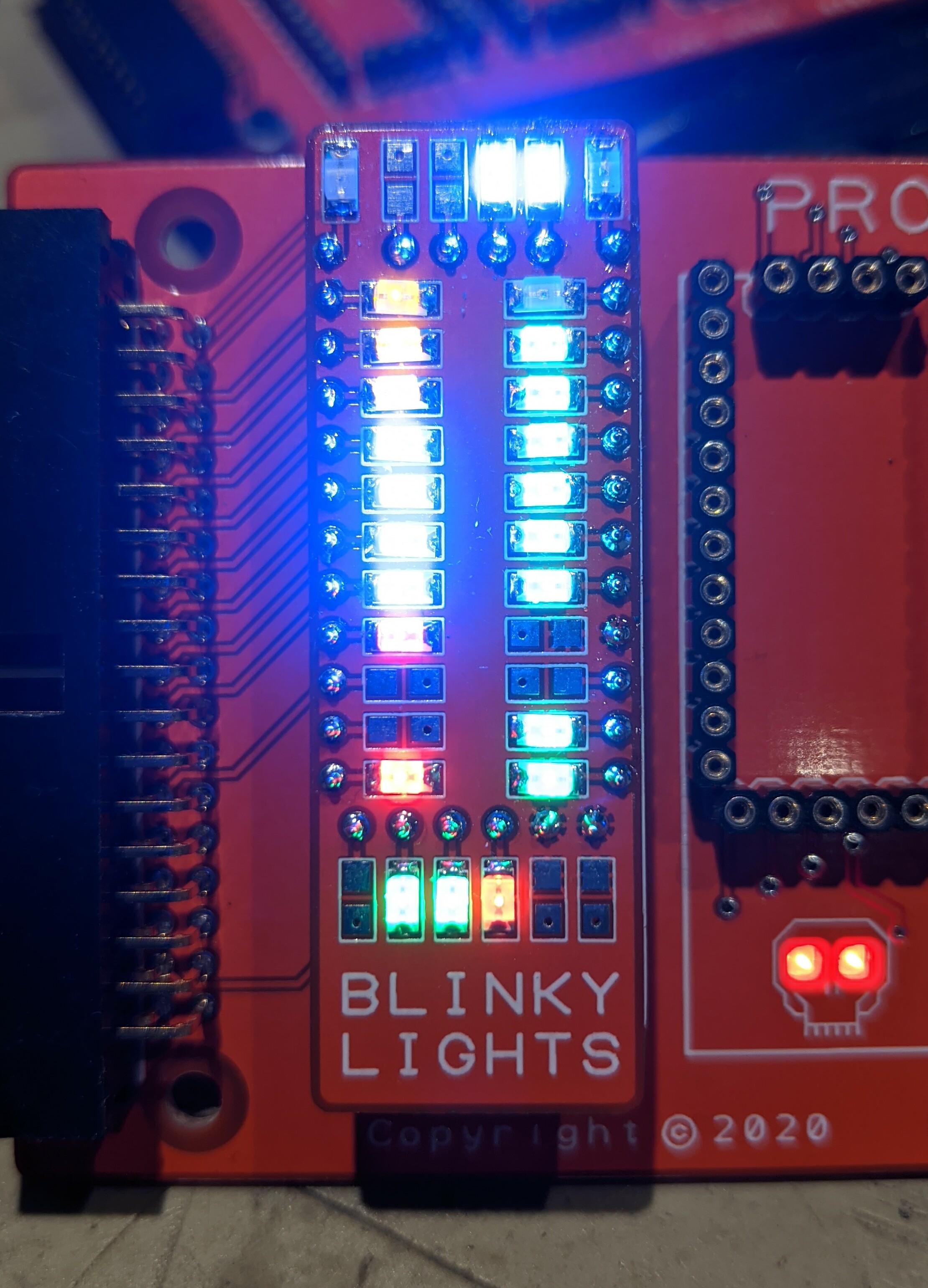
The friend who I work with can design a board entirely in software, we use Pulsonix, without every making a prototype, send it for manufacture, and get working boards back. Even when I build multiple prototypes I often end up with boards that need FECs to make them work.
9
I built these a few years ago to let me use UNO shields with Pro Minis to speed up prototyping. This was an early version. Later versions had more and more features added until I didn't need the shields anymore. That's when my Pro Mini Backplane was born.
10
11
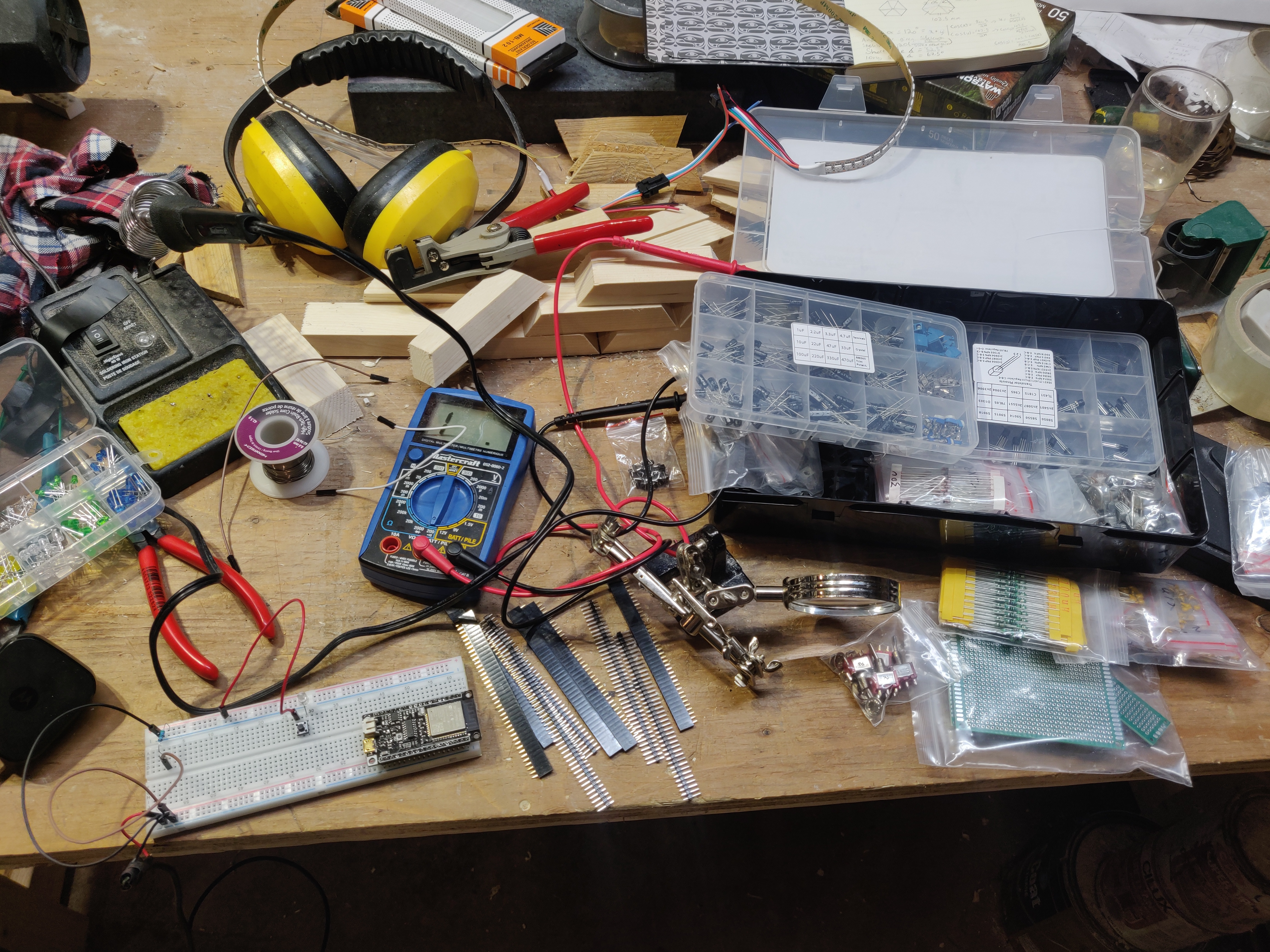
I got some bread boards and a kit full of resistors, caps, LEDs, etc. On Amazon, and 3 esp32s (dfRobot boards) from digikey. Very exciting! I already blew an LED (current limiting resistor? Never heard of her!)
12
I had a gap in the wall from where an old monitor mount used to be attached so wanted to make something to cover it up.
The LEDs are controlled by an ESP8622 running WLED, monitor data from the PC comes from Hyperion software. It can be set to a constant color, dozens of set themes, or match the color output of whatever is on my monitor.


The microcontroller sits under the desk and receives constant power, it is the wired to a button on my desk to turn on/off power to the LEDs.


Laser cutter action:

I tried to give it an aged rock/stone appearance using some textured spray paint which actually turned out pretty well. I think some of that doesn't come across well in the photos, but in person it looks good (to me anyway).
LEDs changing color https://imgur.com/a/8CmepDk
How to get WLED running: https://tynick.com/blog/11-03-2019/getting-started-with-wled-on-esp8266/
More info about Hyperion https://docs.hyperion-project.org/en/user/leddevices/
cross-posted from my post here: https://lemm.ee/post/1063150

13
cross-posted from laser cutting community !lasercutting@lemm.ee : https://lemm.ee/post/896795
This was my first real dive into Arduino and multiple button mapping. It took a significant amount of trouble shooting and learning the software to get things to map to the computer action.
Gif of the action https://imgur.com/a/XI9KTeH
Prototype 1:Started this project before I had a laser cutter and had tried to just drill through acrylic. It didn't work well, but it held my buttons during testing
Prototype 2 Still no laser cutter but I cut out using plywood worked much better for manually cutting out the holes
Prototype 3 Much better


14
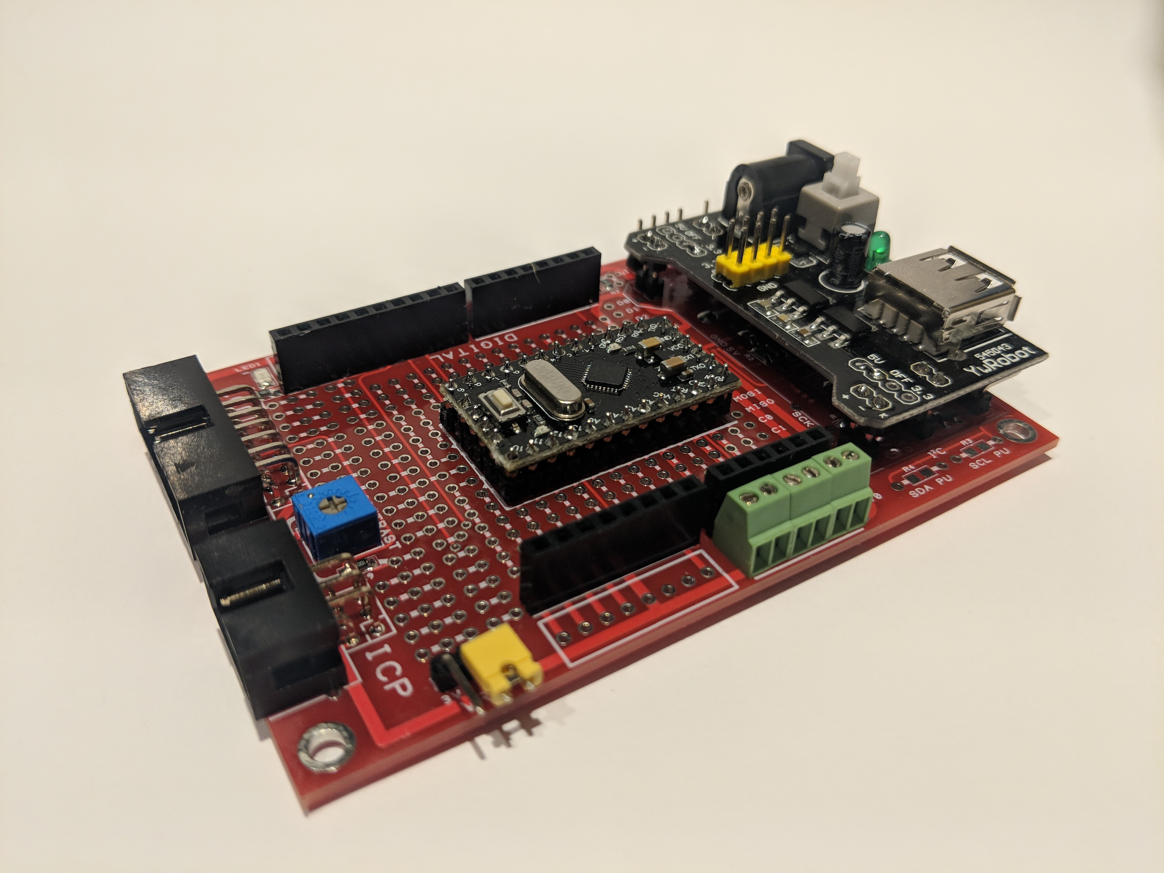
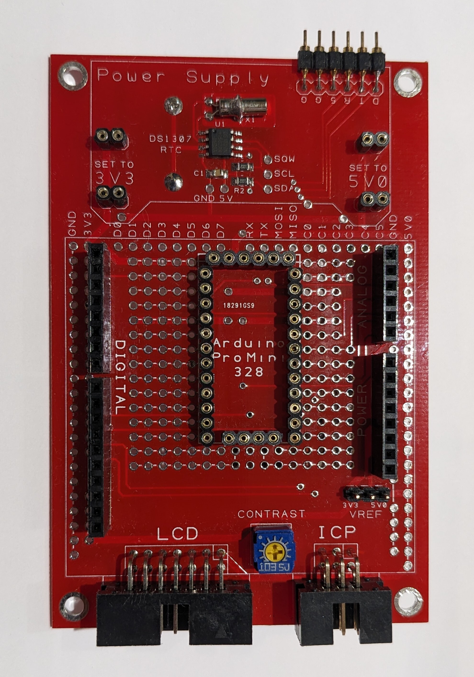
This is an early version of the board that I created because I was irritated by the fact that there were no shields available for the ProMini. It includes the ability to plug in one of those cheap, Chinese breadboard power supply boards and I stuck a DS1307 real time clock under it. The ProMini goes in the center then you can plug regular UNO shields into the carrier. These things worked well but I decided to make a bunch of shields specifically for the ProMini.
15
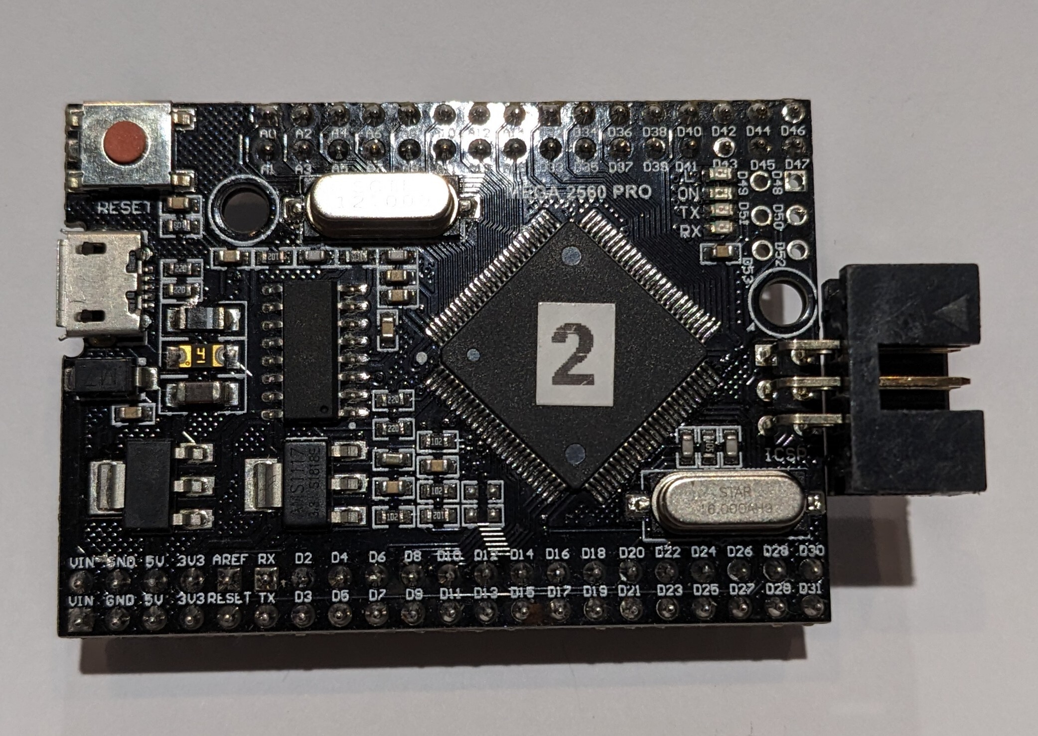
This is the big daddy of Pro Minis. I have a bunch of these in my Arduino bin and in my biggest project, the Maple Syrup machine room that I call the SapMaster.
This board uses a micro-USB connector, ATMEGA2560, and a CH340G USB to serial chip.
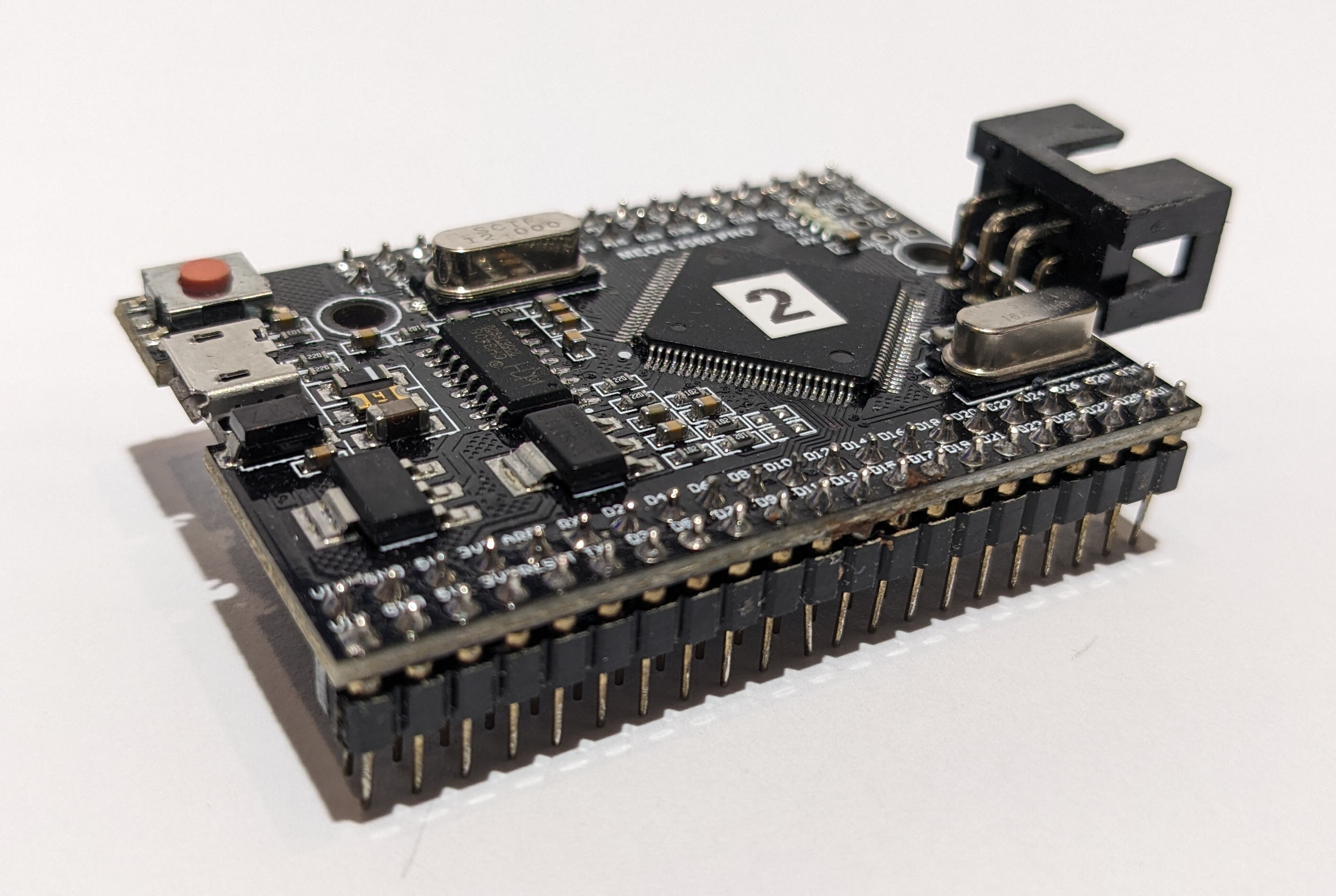
This is an extremely capable chip. I pair it with an ESP32 and a dual FRAM board in the SapMaster controller.
16
I have a boat load of these in my Arduino bin and spread around in various projects.
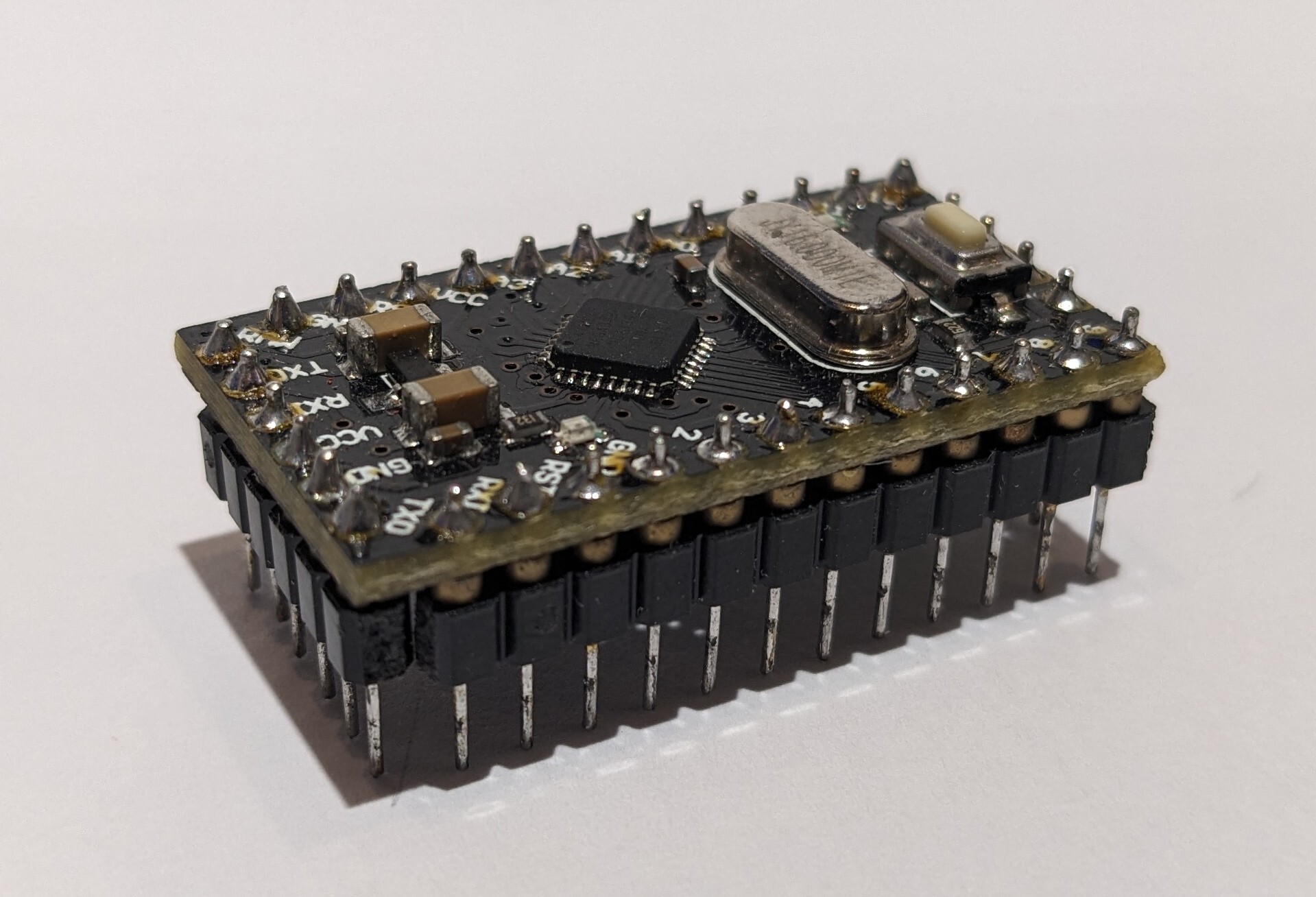
This particular ProMini is based on an ATMEGA328P but I also have ATMEGA168s as well. This is a bare bones Arduino with no ICP port, no USB port, no power regulation, no nothing. This is just a 328P with a bit of supporting circuitry.
17
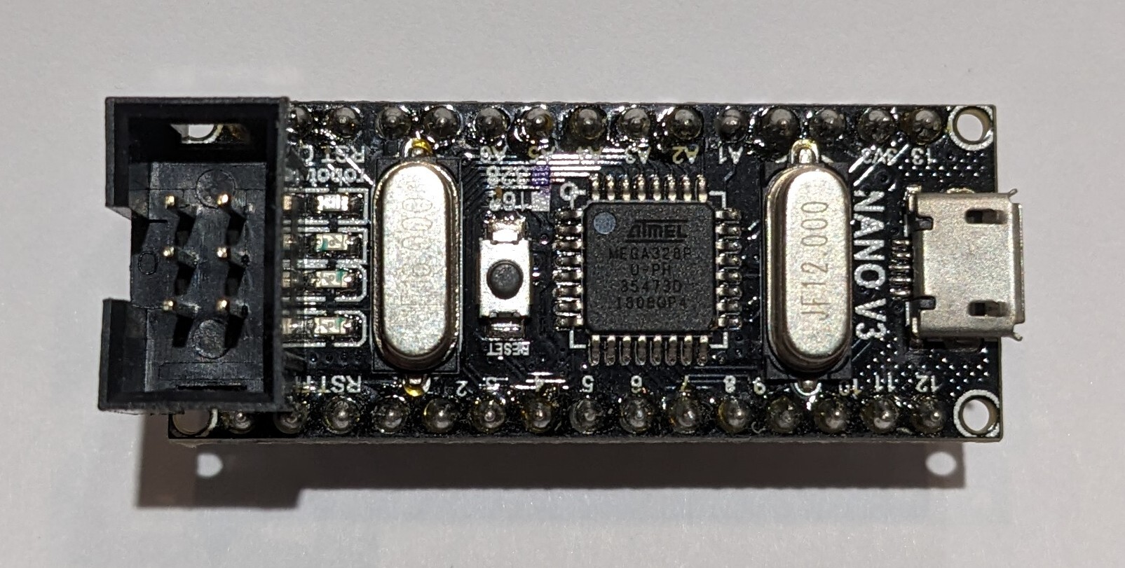
There are a bunch of these in my Arduino bin and in one project or another. My maple syrup machine started on an UNO but ran on a NANO V3 for several years before moving to a MEGA2560 Pro Mini.
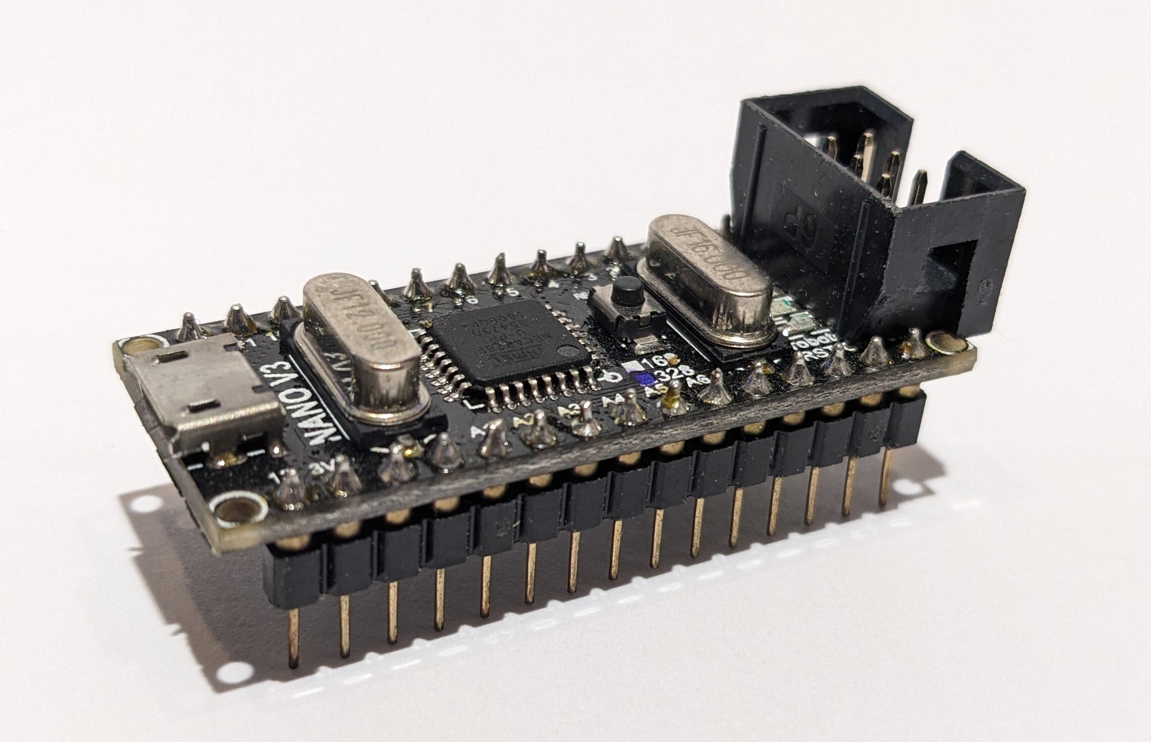
This board uses a micro-USB port, a surface mount ATMEGA328P, and a CH340G USB to serial chip.
18
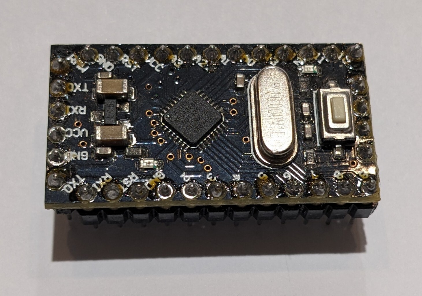
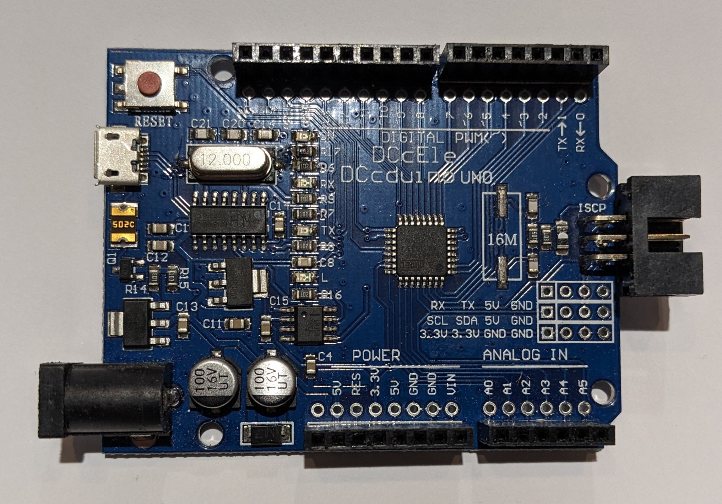
I have a few of these in my Arduino bin.
This one has a micro-USB connector, surface mount ATMEGA328P, and a CH340G USB to serial chip.
19
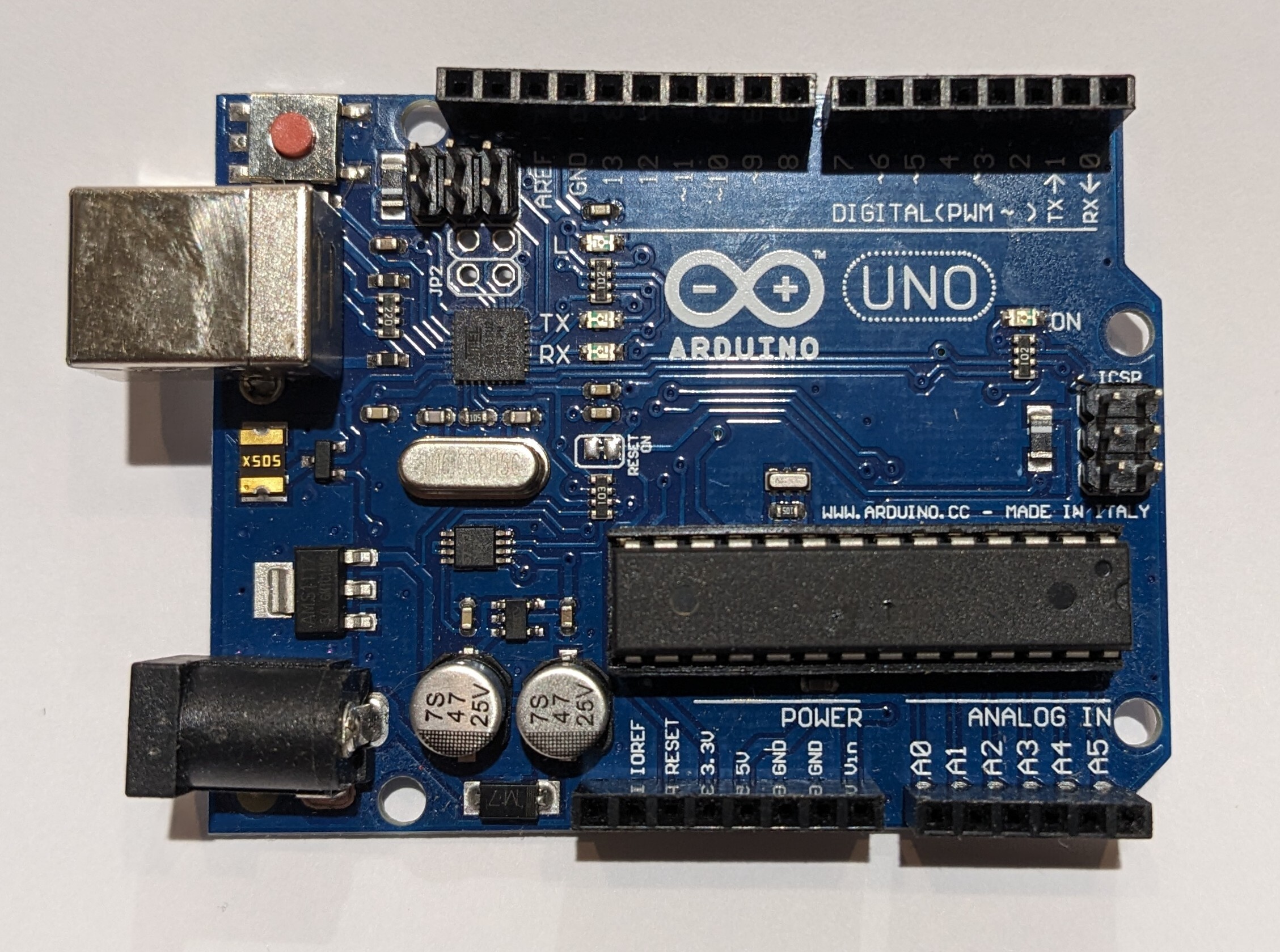
I have a few of these in my Arduino bin.
They have the classic USB-B connector, a DIP-28 ATMEGA328 chip, and a MEGA16 to so USB to serial conversion.
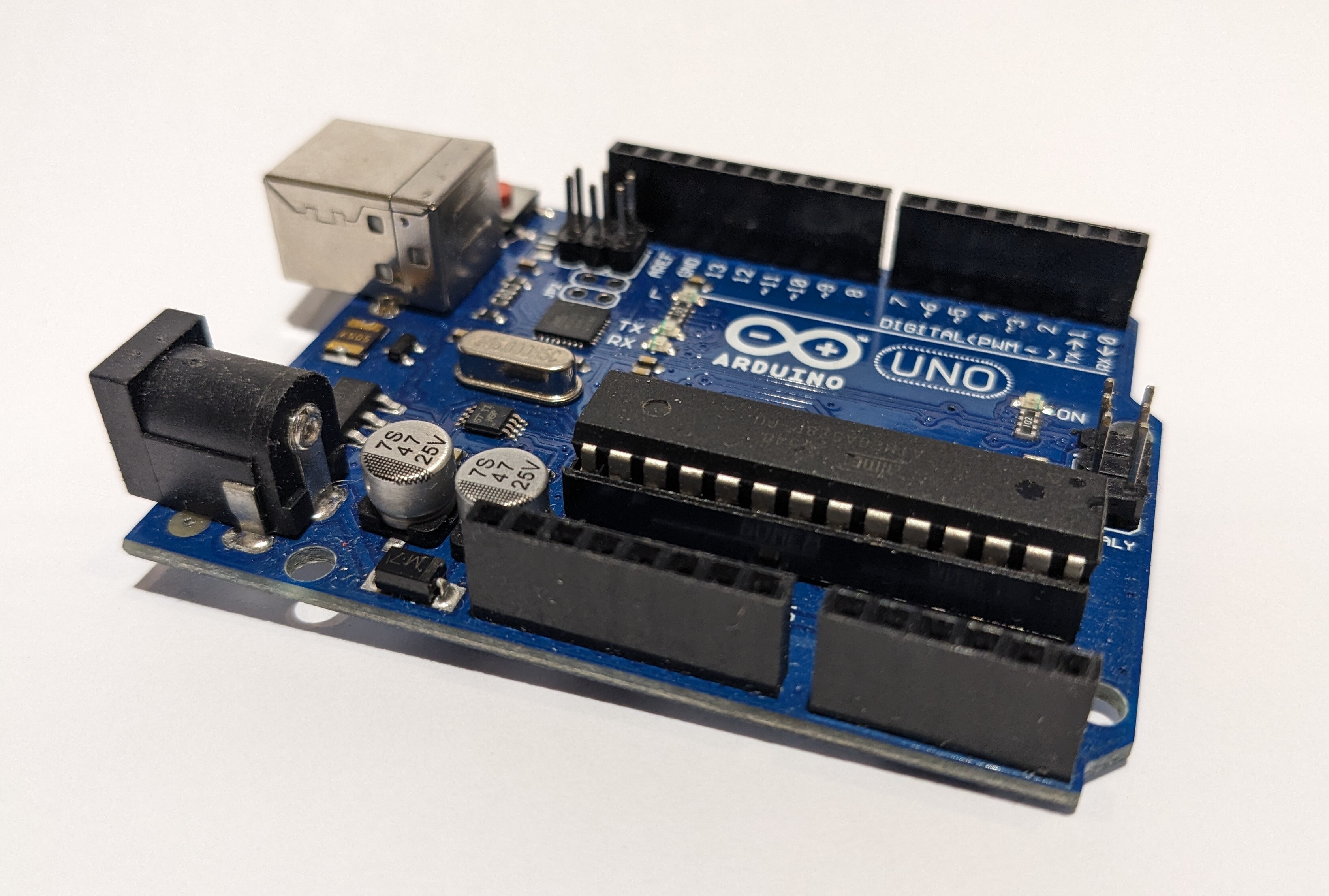
This board is a workhorse.
20
21
I was working on a number of projects that used the ProMini as the microcontroller. I was irritated by the lack of shields specifically for the ProMini.
First, I designed a board that I called my ProMini Sheid Carrier which had a power supply, an RTC, some LEDS, a place to plug in one of those cheap, Chinese breadboard power supplies, and connectors for a regular UNO style shield.

(Click the pictures for a higher resolution version.)
What I really wanted, though, was shields designed specifically for the ProMini.
So...I designed them.
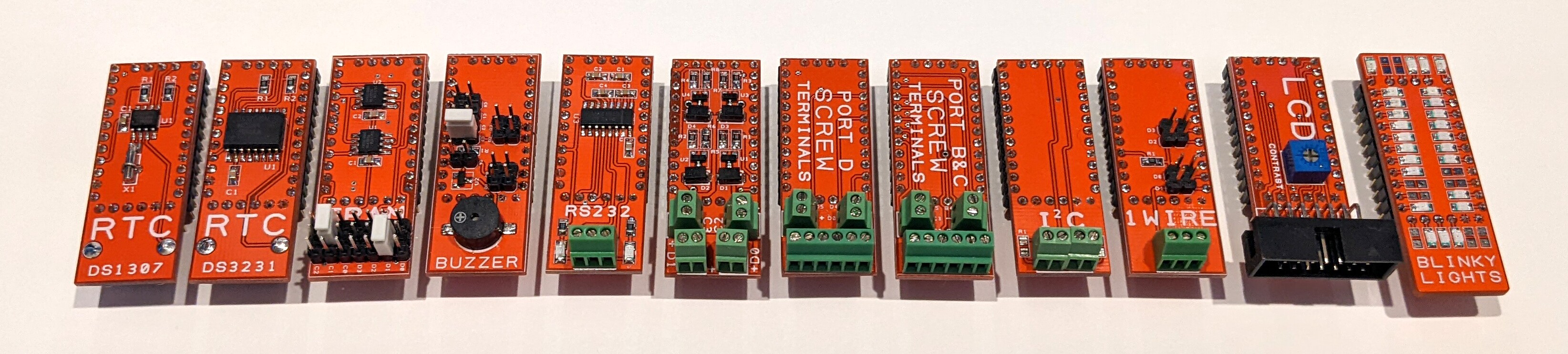
In the cover photo are (from left to right):
DS1307 Real Time Clock with Battery Backup DS3231 High Precision Real Time Clock with Battery Backup Dual FRAM (or other memory with the same pinout) Buzzer RS232 Transistor Driver Port D Screw Terminals Port B & C Screw Terminals I^2^C 1 Wire LCD with Contrast (ETTeam Connector) Blinky Lights
At first I made them stackable, like UNO shields...

but that looked stupid.
So I designed a ProMini Backplane board that would carry them.

The backplane includes 6 slots. The boards can go in any slot but the PSU slot has a couple of extra pins to bring down regulated 5V and 3.3V for the screw terminals and jumpers to select which regulated voltage goes to the Vcc line. The ProMini slot next to the PSU slot has a jumper to disconnect Vraw from the ProMini so it can be powered by the regulated supply voltage of your choice. The board also includes a 6-pin ICP slot and they can be daisy-chained together to add slots.
I had a lot of fun designing all of these boards and putting them together.
I put together these kits for my kids. They include one of each board, a breadboard, a USBasp, a programming cable, some Dupont wires, a 1602 LCD and LCD cable, and a little homemade button pad and strip of 8 LEDs with resistors.

22
ESP8266 and a 2.4 inch touch screen. The button turns on and off the LED backlight on the screen.
Inside the base is a charging station that powers the weather display, 2x USB C and the galaxy 4 watch base.
The base is made of layers of plywood cut out on my laser cutter.
Weather station code by Daniel Eichhorn https://github.com/ThingPulse/esp8266-weather-station-color


Weather info is grabbed from Openweathermap, you can sign up for their free API key
Source code https://github.com/ThingPulse/esp8266-weather-station-color/blob/master/esp8266-weather-station-color.ino
I was using adafruit hardware so used their guide/libraries https://learn.adafruit.com/wifi-weather-station-with-tft-display
I had to remove some of their touchscreen calibration code since it seemed to be causing things to get hung up in a loop when turned on.
I also had to adjust the rotation 180degrees so the ESP attached to the back of the screen was at the bottom instead of the top to fit it in the enclosure.
I use pin 5 to toggle the LED backlight.

23
Most of the projects I design start out on solderless breadboards. The one in the bottom of this picture is a ROM switcher and reset circuit for a Commodore 64 that I'm working on. This circuit will fit inside the footprint of a 27256 ROM chip in a 2364 to 27256 ROM adapter.
Other projects are larger like this early prototype of my maple syrup machine room controller, the SapMaster...

or this...something...that I was doing with an ESP32 and a Raspberry Pi Zero W.

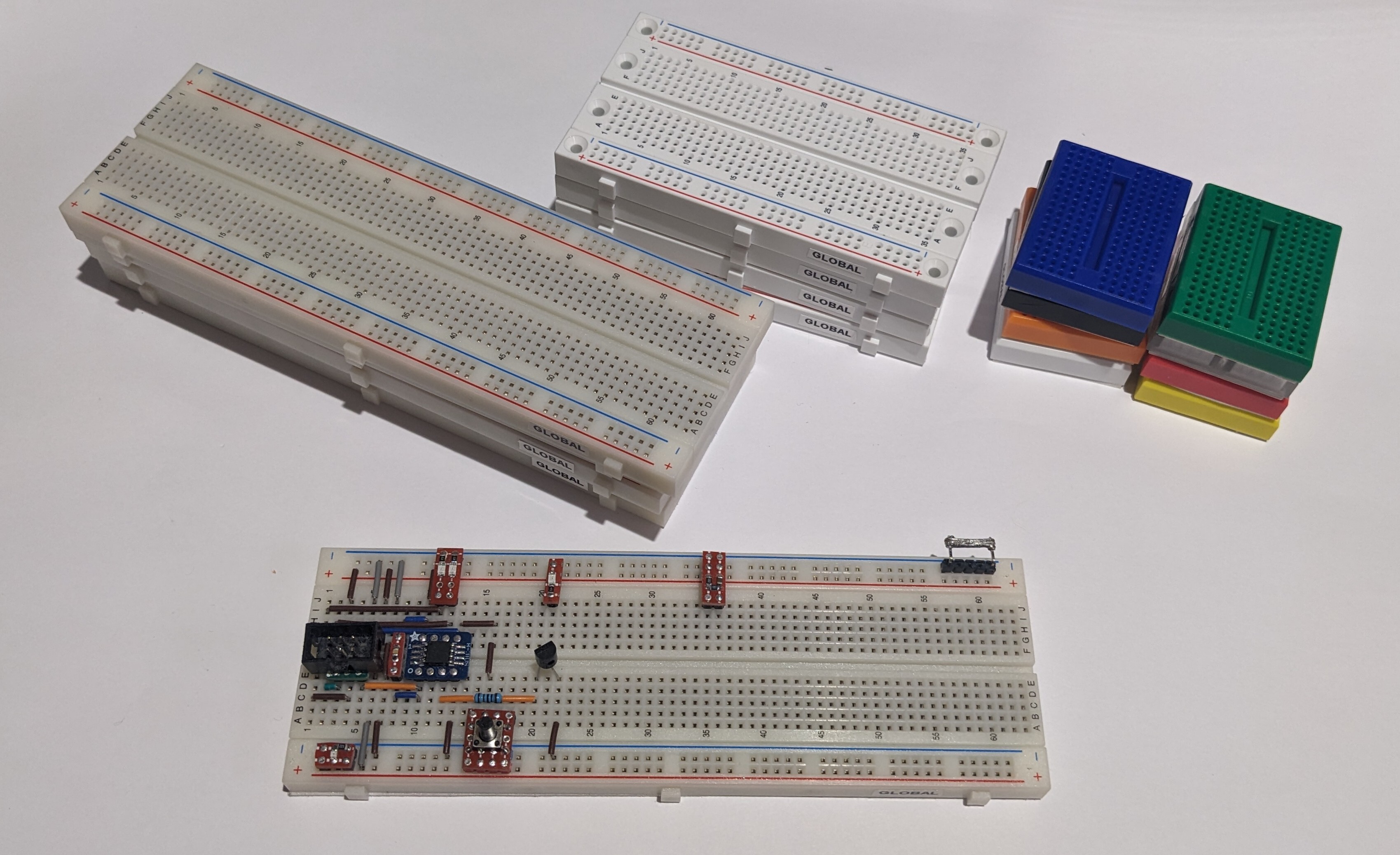
Over the years I've collected a number of solderless breadboards. Some I bought myself and others came with kits that I bought. A number of them came from Hacker Boxes when I had a subscription before the pandemic. I had the delivered to a UPS store in Ogdensburg, NY and drove over and picked them up once a month. Hacker Boxes are cool. Definitely check them out.
Some of the solderless breadboards in my BREADBOARD drawer were cheap, Chinese knock-off breadboards. They had...issues...

not to mention the fact that the contacts were SUPER cheap. They often didn't line up well with the holes and prevented pins from being plugged in. Dupont wires and header strips were a BIG challenge and when plugging in a header strip the contacts often stretched and didn't spring back properly.
I finally decided that it was time to replace all my cheap breadboards with better ones.
The cheap ones can be bought on AliExpress for CAD$2. The better ones cost in the neighborhood of CAD$10. I spent some time doing research and talking to friends in the electronics business and settled on Global Specialties (pictured above.) Just about any of the brands available from Digikey or Mouser will be the same quality.
The contacts are nickel plated phosphor bronze and are rated for 1.5A at 36V.
I've switched my prototypes over to the new breadboards and am very happy with how the feel.
24
25
cross-posted from: https://lemmy.ca/post/703695
Yesterday I posted a picture of a little tact switch that I installed on a piece of protoboard with a hardware debounce circuit on the bottom. I love those little things and thought I would share a how to for making them.
The first thing you need is the little piece of PCB. I had a bunch of these Altoids Tin protoboards made up a few years ago.

I break them down into smaller pieces,

then I break those down to the size that I need,

then I sand the edges to make them pretty (and also to make them small enough to sit beside each other if I need more than one.

Note that the board consists of four columns of 3 connected pads and four columns of 2 connected pins.
Next, I assemble (almost) all of the components that I'm going to need. These are (top to bottom, left to right) 1 uF 0804 capacitors, 1 K 0804 resistors, and 10 K 0804 resistors, the little sanded piece of PCB, three r-pin pieces of header strip (I like to use one red, one blue, and one black but you can use all black or any other color you want), and a 5 mm x 5 mm tact switch (I like the ones with the 7 mm shaft as shown because I can put a cap on them but any old tact switch will do.) Missing from this picture is a

First, we're going to install the debounce components on the bottom of the board. With the columns of 2 at the top and the columns of 3 at the bottom you're going to bridge the gap on the second column with the little jumper wire and the third column with the 10 K resistor. Next you're going to bridge the top end (at the 2-pin column side) of the little wire and the 10 K resistor with the 1 uF capacitor. Finally, you're going to bridge the bottom of the right two 2-pin columns from the pint where the 1 uF capacitor and 10 K resistor meet to the bottom of the last column leaving the hole unobstructed. It will look like this:


The next part is tricky. You have to push some of the pins on the header strips through. On the black one and the red one (or two of the black ones) you're going to push three of the pins through from the long side. On the blue one you're going to push through one of the pins from the long side as shown.

Now, push the header strips into a breadboard as shown. The pins that you pushed through do not go into the breadboard, they stick up into the air. It's important that the pins that you didn't push through on the red and black strips line up with the one that you did push through on the blue strip as shown.

Next, put the PCB over the pins as shown. The soldered components should be on the bottom of the board facing the breadboard. Make sure that the point where the capacitor and two resistors meet is in line with the three special pins on the header strips. If thy don't you can turn all of the header strips around and try again.

Next, clip the pins you pushed through, the ones stick up into the air, off flush with the PCB.

Now, push the ends of the short pins you didn't push through and cut off down flush with the surface of the PCB.

Check one more time that the three special pins and the point where the three components meet are lined up then solder the pins marked with an X.

Now, grab your tact switch. Note that the legs have bumps in them to help hold them in the holes while you solder them.

Use a pair of smooth jawed plyers to squeeze the legs straight then bend two pins out at 90 degree angles as shown.

Trim off the ends of the pins you bent.

Insert the tack switch into the PCB as shown. The bent pins will be over the two pins in the blue row that you didn't solder above. You will need to bend the bent pins out a bit to make them reach the middle of the pads.

Now, solder all four pins pushing down on the body of the switch to make sure it's tight to the PCB and lined up square to the board.
Once you've soldered the switch in place flip it over and make sure that there is a good connection between the end of the 1 K resistor and the pin of the switch. Add a bit of solder if you need to.

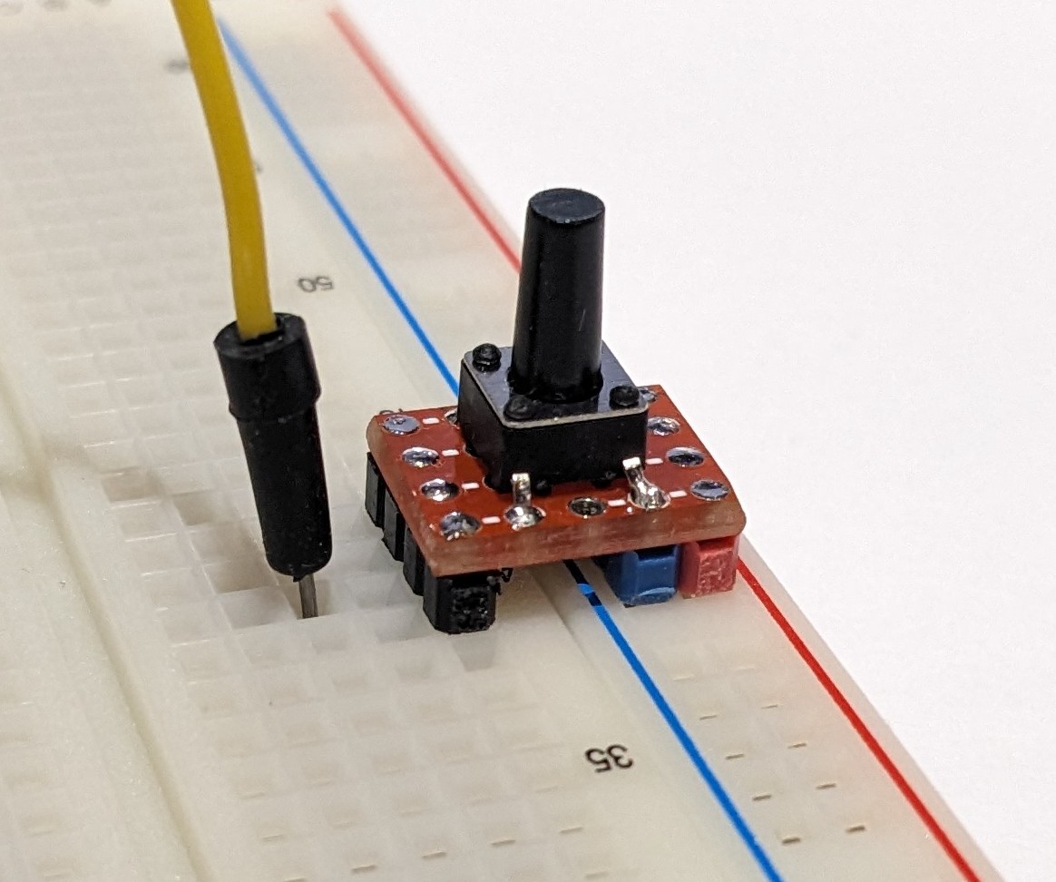
Now you can plug the switch into your breadboard and add a Dupont wire or jumper wire to the pin of your MCU.

Note that the red header strip and blue header strip match up with the red and blue rails on the breadboard. This switch can only be installed on this side of the breadboard to get a debounced going low switch. The construction of a switch for the other side of the breadboard is exactly the same but you switch the position of the red and blue header strips.
This is what one of these little switches looks like in a project. This is a prototype for a ROM switching and RESET circuit I'm going to build into a 23xx to 27256 ROM adapter for the Commodore 64.

view more: next ›