tbe

joined 1 year ago
[–] tbe@lemmy.world 0 points 1 year ago (1 children)
[–] tbe@lemmy.world 1 points 1 year ago* (last edited 1 year ago)

Mine is the smallest one of a series of these, it has two heating elements inside.

I don’t have it for that long but I didn’t have problems so far, I’m usually only making rather small PCBs tho. I did make some recommended modifications like replacing the paper insulation tape with a kapton tape, proper grounding and flashed another firmware.

I did only use a small hotplate and/or a hotair station, so it seems to be definitely a stepup here 😌.

[–] tbe@lemmy.world 0 points 1 year ago* (last edited 1 year ago) (2 children)

Yeah I have such a small, cheap Chinese one (T962) that I modified and flashed a nicer firmware on.

I basically populated the bottom side (with more components) first after applying solder past with a stencil, then reflowed the board. After cooling down I applied the solder paste to the upper side (with the LED) by using a small needle on a syringe (because using a stencil was too weird since the board wasn’t laying flat) but since the pads are relatively large and not that many that worked fine. Then I placed the components on that side and simply run the reflow cycle again.

I started with the bottom side because there are no heavy components. I expected heavy parts to just fall off on the second reflow cycle so I tried to avoid that.

At the end I manually assembled the USB connector using a regular soldering iron and tons of flux gel.


I’m currently working on a more complex project that uses double sided assembly (and a weird USB-C connector). To practice these things a little, I ordered some low cost boards to get used to that connector and explore double sided reflow (which seems easier than I expected).

For those who are interested, this is a reference design from framework computer for their expansion card system. It can be programmed with circuitpython or Arduino and utilises a SAMD21 microcontroller.
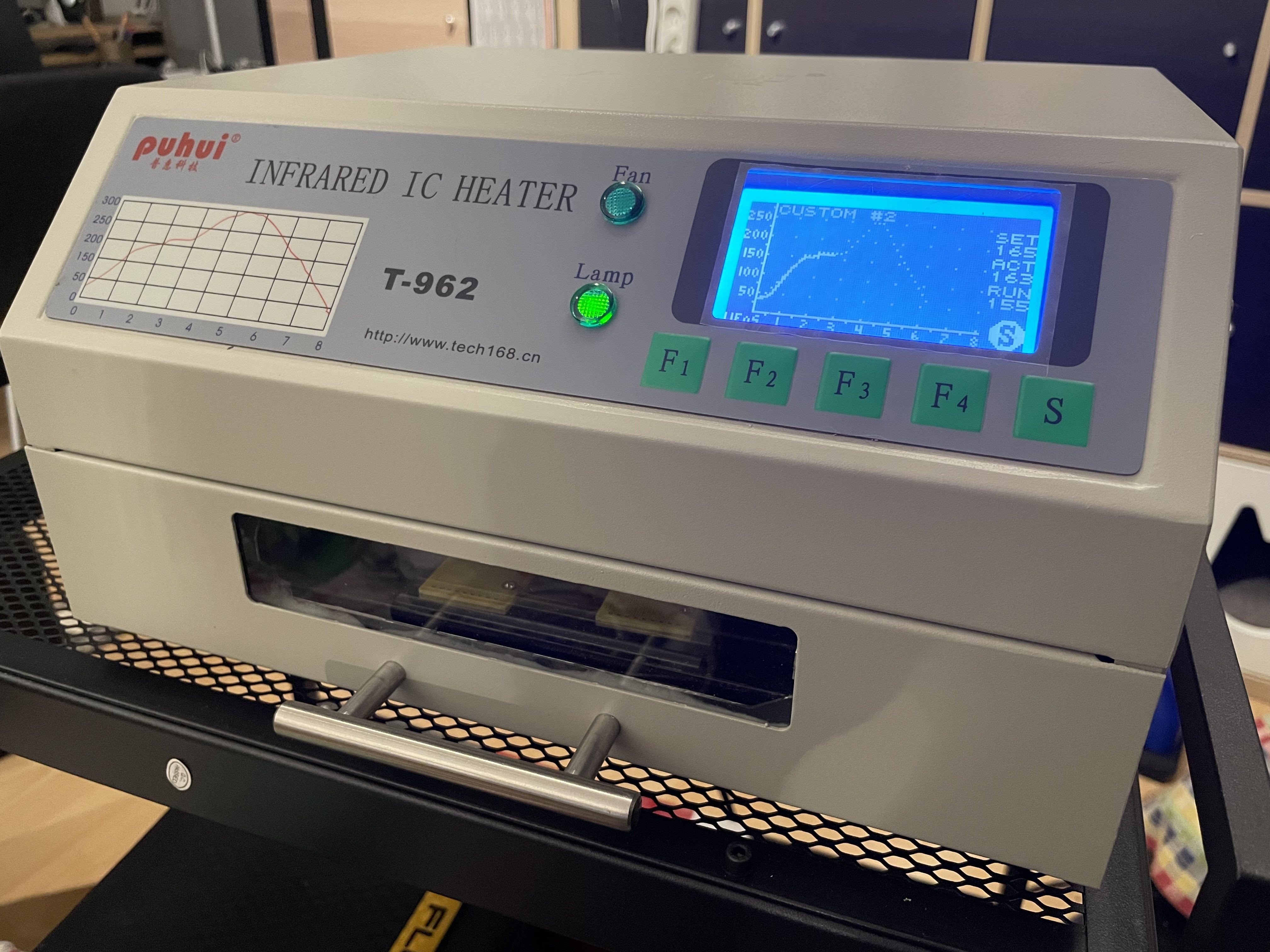