Soldering

462 readers
1 users here now

This community is for electronic hobbyists to discuss projects and is focused on soldering. Everyone is welcome from the noob to people who have been soldering as a hobby for decades to people who solder professionally. We'll talk about materials and techniques, equipment, and projects. Everyone is welcome. All questions are welcome. Post photos and ask for help.

RULES:

  1. All Lemmy.ca rules apply here.

  2. Everyone (see rule 98) is welcome.

  3. If you’ve seen a question 100 times answer it the 101st time or ignore it. Even better, write a complete, detailed answer and suggest that the mod(s) pin it to the community.

[Did you actually think there were 98 rules?]

  1. If you present something as fact and are asked to provide proof or a source provide proof or a source. Proof must be from a reliable source. If you fail to provide proof or a source your post or comment may be removed.

  2. Don’t be a dick. Yes, this is a catch-all rule.

  3. The mod(s) have the final say.

founded 1 year ago
MODERATORS
26
1
submitted 1 year ago* (last edited 1 year ago) by MapleEngineer@lemmy.ca to c/soldering@lemmy.ca


When I first started soldering my parents bought me a (probably < $10 at the time) hobby soldering iron. That iron took a beating and was replaced with another hobby iron then another. I ended up with a hobby iron that I absolutely loved. It had a powder blue handle, a solid barrel (not rolled sheet) and was flared where the handle met the barrel. I used that iron for many years. I am not sure where it went. It may be in a box of tools somewhere or it may be gone for good.

I'm not sure exactly when I got my Weller WESD51 soldering station. It will have been between 15 and 20 years ago. At around $150 it was an expensive upgrade for me. That original station still sits on my desk and up until a few weeks ago was the only station on my desk.

image

I normally have an ETA (1.6 mm chisel) tip in the PES51. It meets most of my day-to-day soldering needs. I find that I can easily solder SMDs down to 0805, SOT23s, and SOICs with the ETA.

image

When I'm doing something like a QFP of TQFP I switch to a ETGW (2 mm beveled cup) tip. The ETGQ style Gullwing tip is the tip professionals use to hand solder chips with gullwing style pins.

Yes, this tip is a little bit oxidized.

image

I cleaned out the solder to show the cup in the photo. Immediately after I took this photo I fluxed and tinned the tip. It's all good and ready for the next time I use it.

image

I have a range of other tips that I use from time to time when they are appropriate. They include (upper left to right then lower left to right):

ETAA - a 1.6 mm bevel

ETL - a long, heavy 2 mm chisel

ETR - a long, light 1.6 mm chisel

ETT - a 0.6 mm conical

ETU - a 0.4 mm bevel

ETX - a 0.2 mm bent conical

TETS - 0.4 mm long conical

The projects that I've been taking in recently (I don't call them jobs because I often do them for free) have been more complex. I've had to desolder SMD electrolytic capacitors and I've been soldering 0.4 mm pitch TQFPs. I needed a soldering station with a bit more range.

A few weeks ago my Hakko FM-203 arrived with the pair of FM-2027s you see in the cover photo. The green one is loaded with a T15-BCM2 which is a 2 mm beveled cup like the ETGW on the Weller and the yellow with a T15-D16 which is a 1.6 mm chisel like the ETA on the Weller.

I'm planning to add a FM-2022 tweezers at some point in the near future to help with those pesky SMD electrolytics.

27
1
submitted 1 year ago* (last edited 1 year ago) by MapleEngineer@lemmy.ca to c/soldering@lemmy.ca


This was an interesting repair. The little company that I work with discovered that one of the pins on the TQFP was not pulled out to the header on the breakout board. They needed that pin so they hired someone to desolder it, lift it, and solder a wire on the to cut the trace to one of the header pins and bring the wire out to it.

Unfortunately, the guy they hired to do the work messed it up pretty bad. You can soo the three pins to the right of this repair are damaged. He broke the pin that he was working on clean off the package. They gave it to me to try to save.

First, I rescued the damaged pins as best I could. Then I filed down the edge of the plastic package until I exposed the lead inside and soldered a 0.1 mm bodge wired onto it. I took that wire out to the pin on the header.

This is not an elegant repair but it got them back in business while they waited for a replacement BoB to arrive. I think they are still using this BoB for their development.

I do these fine repairs under an Olympus SZ40 microscope with a ring light.

image

I always wanted an optical soldering microscope but could never justify the cost. I found this one in a microscope shop in Montreal for $200. For that price I couldn't not buy it.

28


Most of the projects I design start out on solderless breadboards. The one in the bottom of this picture is a ROM switcher and reset circuit for a Commodore 64 that I'm working on. This circuit will fit inside the footprint of a 27256 ROM chip in a 2364 to 27256 ROM adapter.

Other projects are larger like this early prototype of my maple syrup machine room controller, the SapMaster...

image

or this...something...that I was doing with an ESP32 and a Raspberry Pi Zero W.

image

Over the years I've collected a number of solderless breadboards. Some I bought myself and others came with kits that I bought. A number of them came from Hacker Boxes when I had a subscription before the pandemic. I had the delivered to a UPS store in Ogdensburg, NY and drove over and picked them up once a month. Hacker Boxes are cool. Definitely check them out.

Some of the solderless breadboards in my BREADBOARD drawer were cheap, Chinese knock-off breadboards. They had...issues...

image

not to mention the fact that the contacts were SUPER cheap. They often didn't line up well with the holes and prevented pins from being plugged in. Dupont wires and header strips were a BIG challenge and when plugging in a header strip the contacts often stretched and didn't spring back properly.

I finally decided that it was time to replace all my cheap breadboards with better ones.

The cheap ones can be bought on AliExpress for CAD$2. The better ones cost in the neighborhood of CAD$10. I spent some time doing research and talking to friends in the electronics business and settled on Global Specialties (pictured above.) Just about any of the brands available from Digikey or Mouser will be the same quality.

The contacts are nickel plated phosphor bronze and are rated for 1.5A at 36V.

I've switched my prototypes over to the new breadboards and am very happy with how the feel.

29
1
submitted 1 year ago* (last edited 1 year ago) by MapleEngineer@lemmy.ca to c/soldering@lemmy.ca


A pair of friends, brothers, own a small business manufacturing custom PCBs and systems. The older of the two has always done all of the hardware and the younger the software. The older brother had a heart attack several years ago and has had a shake and weakness in his right hand ever since. He can no longer solder small components so I have taken over that function for him. I love soldering and I love the challenge.

This is a PIC microcontroller that I soldered onto a breakout board for them. It's a 0.5mm pitch (0.5 mm from the center of one pin to the center of another pin) TQFP package. I used a Weller WESD51 soldering station with a PES51 soldering pen and an ETGW angled, cupped soldering tip.

image

I do all of my fine soldering under an Olympus SZ40 binocular microscope that I bought for $200 a couple of years ago from a microscope shop in Montreal.

image

30


Yesterday I posted a picture of a little tact switch that I installed on a piece of protoboard with a hardware debounce circuit on the bottom. I love those little things and thought I would share a how to for making them.

The first thing you need is the little piece of PCB. I had a bunch of these Altoids Tin protoboards made up a few years ago.

image

Full

I break them down into smaller pieces,

image

Full

then I break those down to the size that I need,

image

Full

then I sand the edges to make them pretty (and also to make them small enough to sit beside each other if I need more than one.

image

Full

Note that the board consists of four columns of 3 connected pads and four columns of 2 connected pins.

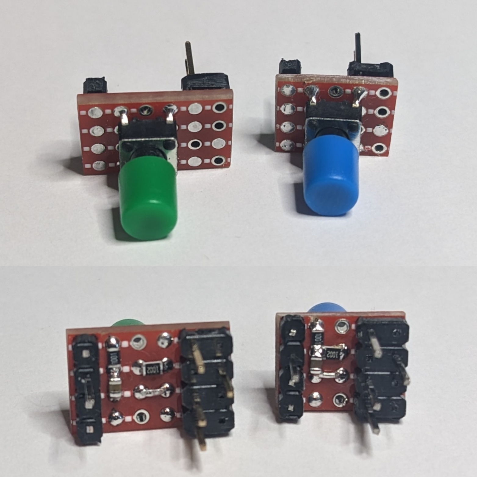
Next, I assemble (almost) all of the components that I'm going to need. These are (top to bottom, left to right) 1 uF 0804 capacitors, 1 K 0804 resistors, and 10 K 0804 resistors, the little sanded piece of PCB, three r-pin pieces of header strip (I like to use one red, one blue, and one black but you can use all black or any other color you want), and a 5 mm x 5 mm tact switch (I like the ones with the 7 mm shaft as shown because I can put a cap on them but any old tact switch will do.) Missing from this picture is a

image

Full

First, we're going to install the debounce components on the bottom of the board. With the columns of 2 at the top and the columns of 3 at the bottom you're going to bridge the gap on the second column with the little jumper wire and the third column with the 10 K resistor. Next you're going to bridge the top end (at the 2-pin column side) of the little wire and the 10 K resistor with the 1 uF capacitor. Finally, you're going to bridge the bottom of the right two 2-pin columns from the pint where the 1 uF capacitor and 10 K resistor meet to the bottom of the last column leaving the hole unobstructed. It will look like this:

image

Full

image

Full

The next part is tricky. You have to push some of the pins on the header strips through. On the black one and the red one (or two of the black ones) you're going to push three of the pins through from the long side. On the blue one you're going to push through one of the pins from the long side as shown.

image

Full

Now, push the header strips into a breadboard as shown. The pins that you pushed through do not go into the breadboard, they stick up into the air. It's important that the pins that you didn't push through on the red and black strips line up with the one that you did push through on the blue strip as shown.

image

Full

Next, put the PCB over the pins as shown. The soldered components should be on the bottom of the board facing the breadboard. Make sure that the point where the capacitor and two resistors meet is in line with the three special pins on the header strips. If thy don't you can turn all of the header strips around and try again.

image

Full

Next, clip the pins you pushed through, the ones stick up into the air, off flush with the PCB.

image

Full

Now, push the ends of the short pins you didn't push through and cut off down flush with the surface of the PCB.

image

Full

Check one more time that the three special pins and the point where the three components meet are lined up then solder the pins marked with an X.

image

Full

Now, grab your tact switch. Note that the legs have bumps in them to help hold them in the holes while you solder them.

image

Full

Use a pair of smooth jawed plyers to squeeze the legs straight then bend two pins out at 90 degree angles as shown.

image

Full

Trim off the ends of the pins you bent.

image

Full

Insert the tack switch into the PCB as shown. The bent pins will be over the two pins in the blue row that you didn't solder above. You will need to bend the bent pins out a bit to make them reach the middle of the pads.

image

Full

Now, solder all four pins pushing down on the body of the switch to make sure it's tight to the PCB and lined up square to the board.

Once you've soldered the switch in place flip it over and make sure that there is a good connection between the end of the 1 K resistor and the pin of the switch. Add a bit of solder if you need to.

image

Full

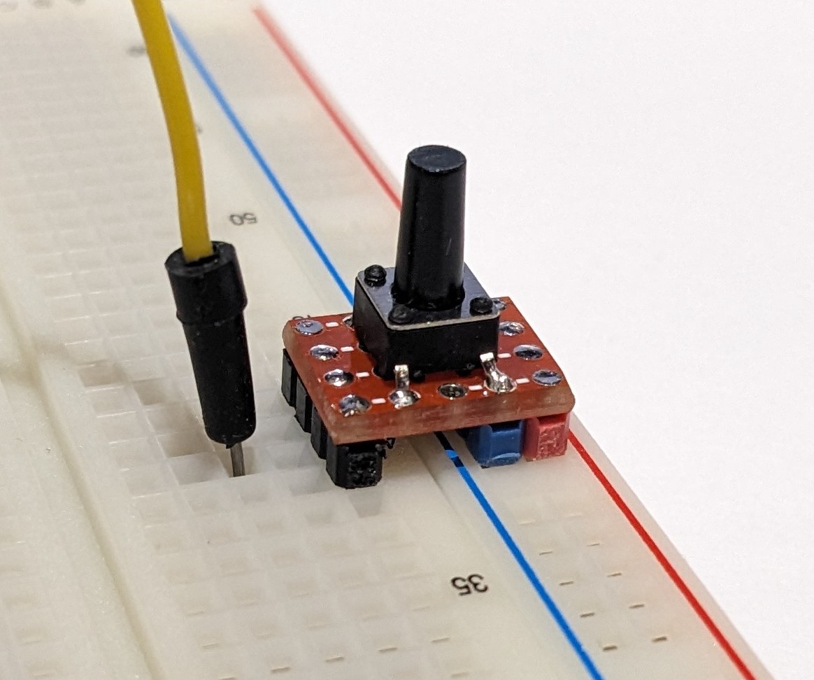
Now you can plug the switch into your breadboard and add a Dupont wire or jumper wire to the pin of your MCU.

image

Full

Note that the red header strip and blue header strip match up with the red and blue rails on the breadboard. This switch can only be installed on this side of the breadboard to get a debounced going low switch. The construction of a switch for the other side of the breadboard is exactly the same but you switch the position of the red and blue header strips.

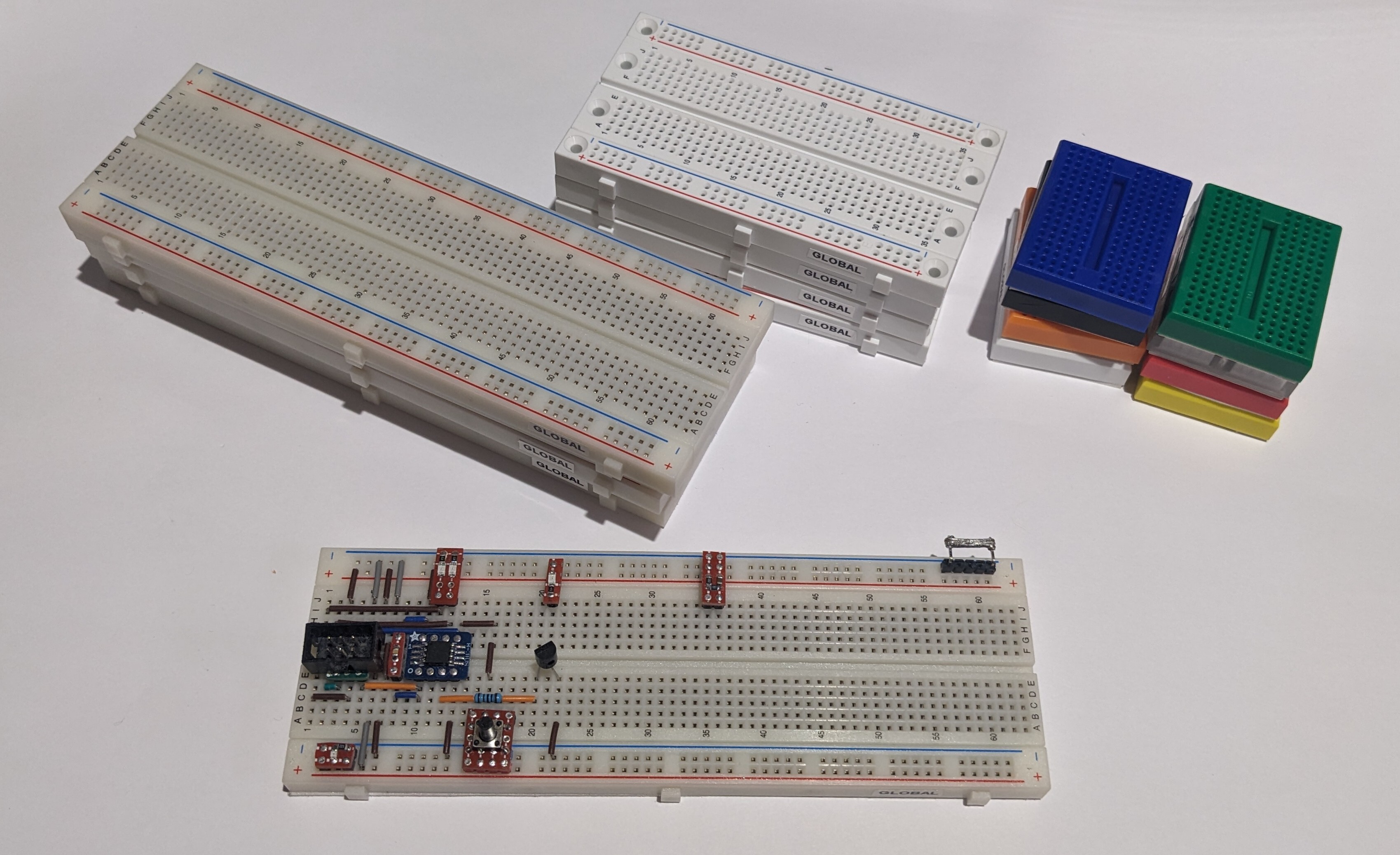
This is what one of these little switches looks like in a project. This is a prototype for a ROM switching and RESET circuit I'm going to build into a 23xx to 27256 ROM adapter for the Commodore 64.

image

Full

31


This is a cool little project. I often prototype circuits on solderless breadboards. I've mostly switched to using 0805 SMD resistors and capacitors. I have a box of 1/4W 1% and a box of 1/2W 1% THT resistors but they aren't neat when they're plugged into the breadboard. I've got 0.1uF capacitors but no 1.0uF in THT.

I decided to make up these little tact switches ready to plug into the breadboard with built in hardware debounce. The debounce circuit also provides a pull-up resistor.

Each switch has a 10K 0805 resistor between Vcc and the MCU pin, a 1.0uF 0805 capacitor between GND and the MCU pin, and a 1K resistor between the switch and the MCU pin. The end result is a nicely debounced going low switch with a built in pull-up. They work great and I can just grab one when I need one and plug it in. I've made versions that will plug into one side or the other of the breadboard so that I can have a switch on either side depending on what works best.

The row with 3 pins is GND and the adjacent row with 1 pin is Vcc. The single pin at the other end is the debounced switched output to the MCU pin.

If anyone's interested I can post pictures of the process of making these and how I wire them up so that the work correctly.

32


I have an ad up on Kijiji saying that I will do electronic repairs. A local gentleman contacted me and said that he had an air hockey table that he had bought that had a broken connector on the controller board. I said I would take a look. I visited him and found that he was in his 80's.

When I opened the controller this is what I found.

I assumed that he probably had the table for his kids or more likely grandkids to play when they visited.

Some super glue, a bunch of scraping, some small pieces of wire, and some careful soldering later and he's back in business.

It turns out that he and his wife play air hockey from time to time.

33


Hello.

I'm MapleEngineer. I'm from Eastern Ontario and I've been soldering for over 40 years as a hobbyist. My user name is MapleEngineer because I'm an artisan maple syrup maker and design and build my own machinery and industrial controllers.

I, like just about everyone, started out with a pencil iron and a bit of solder in a clear plastic tube.

If you're into electronics and soldering please subscribe and feel free to contribute and ask questions.