Hi there
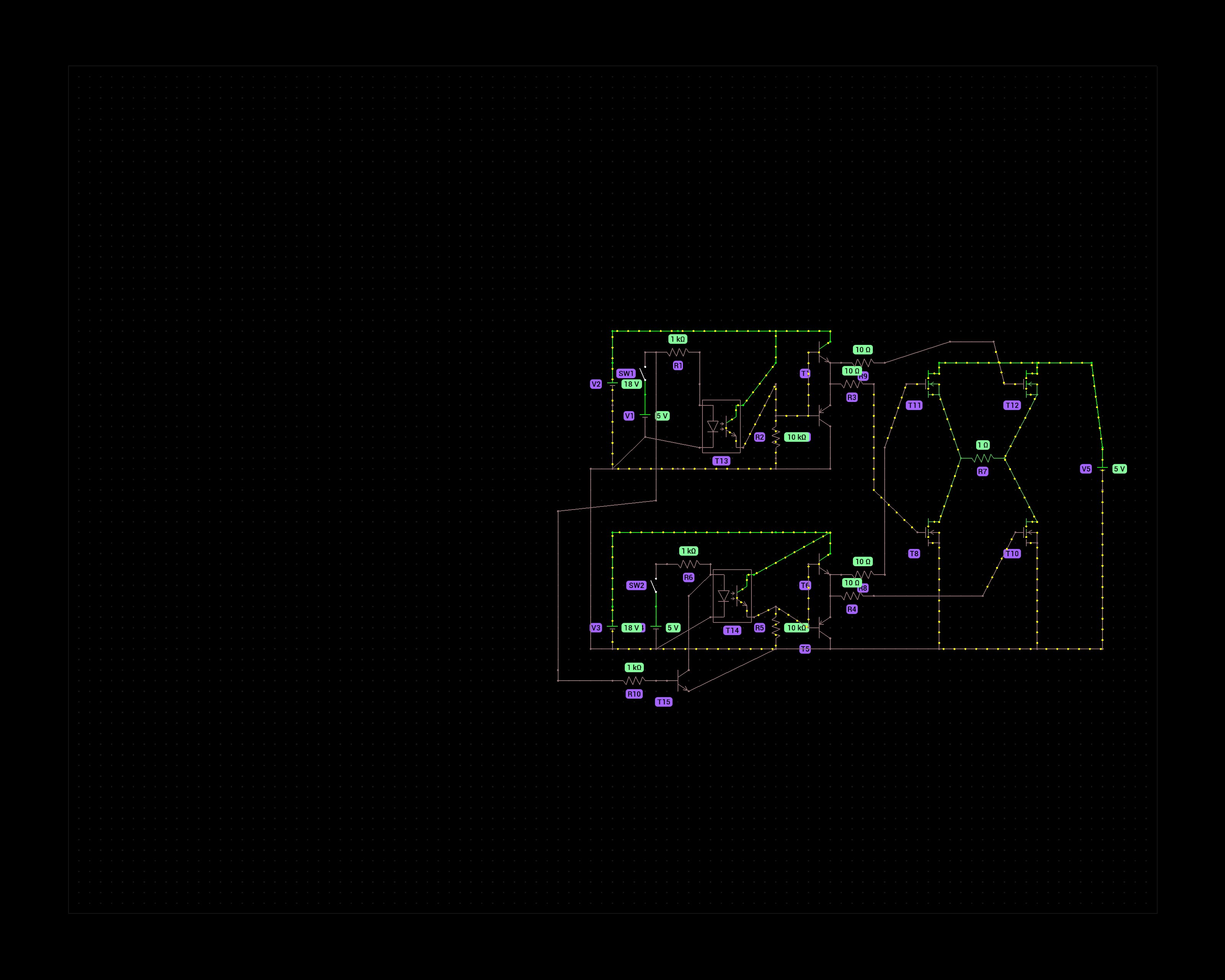
The purpose of this schematic is to control a DC motor that runs at 8V max. That is why I chose 4 N-channel mosfets in the H bridge. P-channels would not fully activate at voltages above -10Vgs but the N-channels can handle 18V at the gate.
The 5v switches represent an Arduino's digital output pins. One to turn forward, one for reverse. To prevent a failure scenario where both pins are HIGH I added a transistor that prevents current from flowing through the optocoupler on the second half bridge.
Does this circuit make sense? I'm not an electronics engineer, just a hobbyist and have doubts about how effective the gate driving circuit is of the mosfets.
Thanks!
Right, sorry about that. I made the simulation on my phone with the Proto app.
I figured the push pull part is good practice with mosfets. It's partially the learning experience and if the motor stalls it could draw several amps.
I won't be doing PWM, just on and off so maybe just the optocoupler is good enough.
I'd have to order dedicated gate drivers and have a lot of 547 and 557 transistors in stock at home.
In that case I would omit the extra transistors and use only the optocouplers.
What sort of application is this? Having 18V somewhere and a 5V supply too that can output several amps is quite unusual.
Well, the whole setup is a semi automatic greenhouse. It has a 12 channel peristaltic pump, grow lights, heater and a plant shaker for pollination. I'm attempting to grow indoor tomatoes and chili's. Not weed although I have learned a lot from weed growers.
The system runs on a 24V power supply so that is easily accessible. The 18V comes from an LM7818 and the motor speed will be regulated with a buck converter module.
I also worry about the LM7818. It drops about 6V, so at 330mA it burns 2W, which seems like the maximum for the package that I quickly pulled up. If you have a very efficient buck converter that gives you at most about 1A to drive the motor. Not a lot of overhead.
Also as I said already, you could just skip the whole thing and make everything work from the 24V using PWM. Since you want to drive it with an arduino that is not a difficult thing.
Good one. I haven´t considered that. The 7818 will only deliver current for very short bursts but perhaps that already is too much. I'll look into the PWM solution.